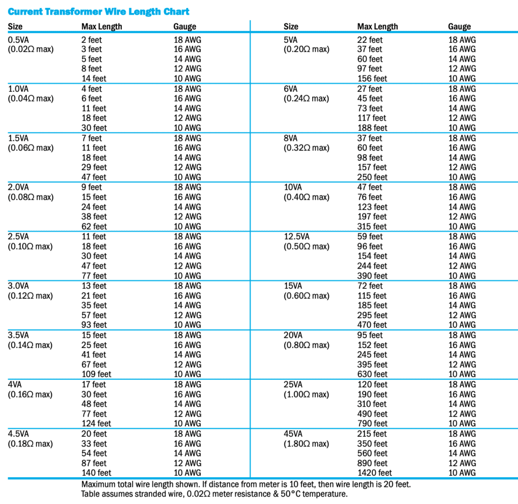
Current transformers are specified by size (VA rating), ratio and accuracy. The VA rating determines the maximum secondary impedance (lead+terminal+meter impedance) that can be driven at the stated accuracy. Metering CTs are specified for a 0.9 power factor at 60Hz. Relaying CTs are specified at a 0.5 PF.
The nameplate ratio assumes that the primary conductor passes once through the transformer window. Large changes in ratio can be achieved by running the conductor through the window more than once. A 300:5 CT with two passes (turns) becomes a 150:5 CT. Three passes yield a 100:5 CT, etc. The accuracy and burden characteristics are unchanged. However, the window must be large enough to accommodate the additional turns of heavy primary wire.
Smaller ratio changes can be made by using additive or subtractive turns on the secondary. On a 5A CT with 1 primary turn, each secondary turn modifies the ratio by 5A. 1 turn additive on a 100:5 CT becomes a 105:5 CT. One turn subtractive becomes a 95:5 CT. An additive turn is wound by running the X1 lead through the window from the H2 to the H1 direction (from the side opposite the polarity mark). A subtractive turn runs the opposite direction (from the side with the polarity mark). For more than 1 primary turn, the effect of secondary turns is also divided by the number of primary turns.
A higher ratio CT generally has better performance characteristics. By adjusting the primary and secondary turns, it can be modified to have a lower ratio while retaining this better performance.

