The Transformer Advantage product family offers a variety of relay options. Some choices are made when the Advantage is specified and ordered. Other choices are made during installation and setup. The following information will help make the best use of this flexibility in units with AMT200 series firmware.
Relay terminology used in the Transformer Advantage documentation:

Normally Energized (NE) or Normally De-energized (ND) refers to the relay coil state when the Advantage is powered and the relay is in the non-alarmed condition.
Setpoint relays are used for control and alarm outputs. Up to 11 form C relays can be ordered by selecting the appropriate code in the fourth digit of the part number. All relays in the Transformer Advantage are single pole. The contacts are rated for 10A (1/2HP) @250Vac or 1A @125Vdc and include AC transient protection. For higher loads or longer relay life, an interposing relay should be used.
The alarm conditions for each setpoint relay are defined at setup. More than one alarm can be linked to a relay. 24 alarms are available in the Advantage, regardless of the number of relays ordered. This allows complex control with minimal wiring. The alarm condition for temperature and current inputs is a signal value ABOVE the setpoint.
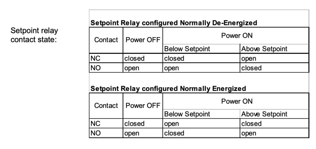
The Advantage automatically runs a periodic sensor and internal self-checks. In addition to the setpoint relays, each Advantage includes an extra relay for a sensor fail (watchdog) function. When a fault is detected, the Sensor Fail Relay (SFR) changes from a normal to an alarm state. Relay 6 is typically set up as the SFR, although any relay can be used. For redundancy in critical applications, more than one relay can be assigned to this function.
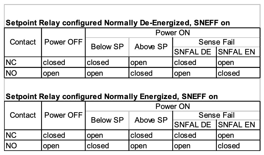
Each setpoint relay will respond to a sensor or internal failure as determined by two configuration variables: Sensor Fail Response (SNFAL) and Sensor Fail Effect (SNEFF). When SNFAL is enabled, the setpoint relay will respond in the manner defined by SNEFF. SNEFF choices are energized (EN), de-energized (DE) or toggle.
Setpoint relays can also be configured to allow a serviceman to test relay operation in the field. Once this feature is enabled on a relay, testing can be done from the front panel or with a laptop using the supplied Advantage Monitoring software.
Relays installed in the Enhanced Transformer Advantage:

The following examples are intended to show some of the features available for relays & alarms in the Transformer Advantage. Contact Weschler’s factory support specialists for assistance in configuring a Transformer Advantage for your application.
Example 1: Set the Advantage to control two fan banks in a failsafe configuration, plus two external alarms. Use a separate service alert to warn of a sensor fail, self-test fail or power loss to the Advantage.
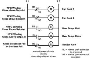
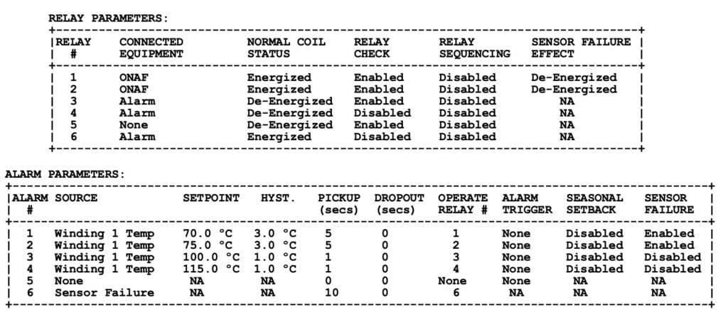
To implement, wire as shown above. Configure 2 relays for cooling fans and 3 relays for external alarms. Define the normal (non-alarmed) coil state for standard or fail-safe mode. Then set up the internal alarms for setpoint, hysteresis & delay. Link each alarm to a relay. Enable sensor failure response & effect for the alarms tied to fan stages.
Notes:
Five setpoint relays ordered (option H). Relay 5 is not used, available as a spare.
1 to 1 alarm: relay association used for convenience.
Relay check disabled on the over-temperature alarm and the sensor fail relay.
Pickup delay applied to reduce rapid cycling and transients.
Enhancement 1: Add cooling and external alarm activation based on top oil temperature. Set Fan Stage 1 to operate at 70° oil; set Over Temperature Alarm for 95° oil.
To implement, enable additional internal alarms and program for the desired top oil temperatures. No change to relay setup needed.

Enhancement 2: Add a pre-cooling function to anticipate the temperature rise from heavy transformer loading.
To implement, program an unused alarm for a winding current setpoint and have it activate the fan relay.

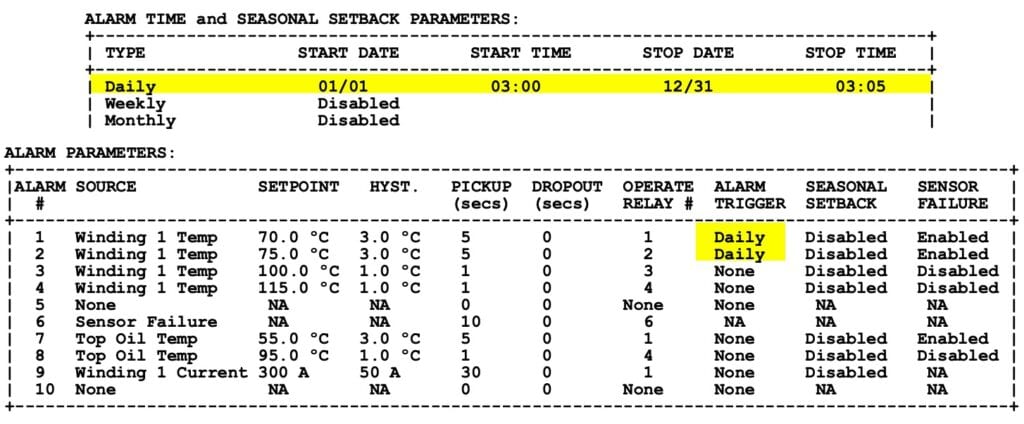
Enhancement 3: Add daily fan exercise to each fan bank.
To implement, set up the daily system time trigger and enable that trigger for alarm 1 and alarm 2.
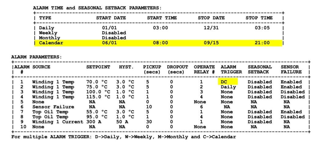
Enhancement 4: Run fan bank 1 continuously in the summer.
To implement, set up the calendar time trigger. Add calendar activation for alarm 1.
Enhancement 5: Activate a relay when an auxiliary input signal exceeds a threshold level.
* To implement, set the channel jumpers on the LCAM module to the correct function & range. In the software, set up the auxiliary input (LCAM) channel for the input signal type and full-scale value. In addition to the 24 setpoint alarms in the Transformer Advantage, each LCAM channel has one alarm available. Set the high and low thresholds (LCAM alarms have dual limits – alarm condition occurs when the signal goes outside these limits). Program it to operate an unused relay (#5 in this example) and configure the relay as an alarm.
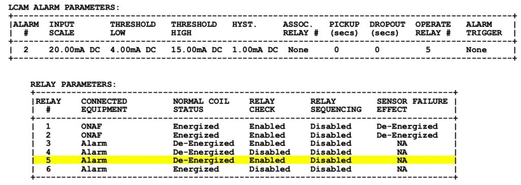
* Requires optional auxiliary analog/digital input. For this example, the Advantage receives a 4-20mA signal from a DG analyzer or an LTC position monitor. Low threshold can be used to detect an out-of-bounds condition or an open input.
Enhancement 6: Use current readback to confirm the operation of a cooling stage.
This enhancement requires an optional analog/digital input and a compatible Weschler current transducer. To implement, clamp the current transducer (CT) around the cooling stage supply wire. Connect the CT leads to an auxiliary input on the LCAM module. Set the LCAM channel jumpers to the 5V range. In the software, set the input scale on the corresponding LCAM alarm to the transducer full-scale rating. Select the high and low thresholds to detect improper operation (such as locked rotor or blown fuse). Associate this channel to the cooling stage being monitored (so the alarm is enabled only when the cooling stage should be on). Add a pickup delay to prevent false alarms due to motor starting current. For a 50A transducer monitoring fan stage 1 and connected to LCAM channel 3:

Cooling stage readback also allows the Advantage to apply the correct gradient when a cooling stage is activated external to the Advantage (e.g. by a manual switch). As programmed above, this LCAM alarm is available on the SCADA digital output. It can also be set up to operate a relay by selecting one in the “Operate Relay #” field. This can be an unused relay, if available, or an additional alarm condition for a relay already in use (e.g. relay 3 in this example).
Enhancement 7: Equalize running time between multiple cooling stages.
For equalization of run time between 2 or more fan stages, a sequencing function can be enabled. Similarly, if there is more than one pump stage, sequencing can be enabled to equalize the run time of the pumps.
To implement, enable sequencing in the relay set up for fan or pump stages. A run time counter in the Advantage tracks operating hours for each stage. At the next call for fan cooling, the fan stage with the fewest hours will turn on.

General Note:
Configuration files have a .txt extension and can be viewed with a text editor (as shown in these examples). To construct a file or make changes, the Configuration app in the Weschler Advantage Software must be used. This software is supplied with each unit and is also available from the Weschler directly.
