Temperature is the most frequently measured physical parameter. A variety of sensors are used to convert temperature into an electrical signal that can be read by electronic instrumentation. Popular temperature sensors include:
Thermocouple
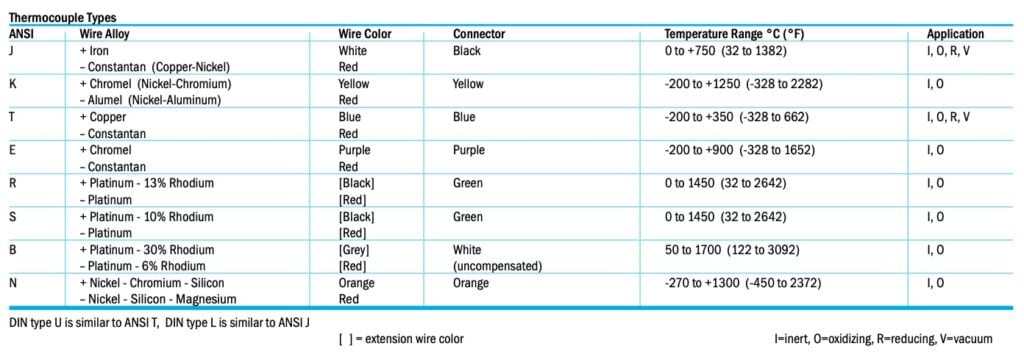
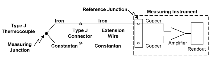
A thermocouple is formed when two dissimilar metal wires are joined together. This creates the measuring junction (also called the hot junction). A small voltage is generated at this junction due to the Seebeck effect. This voltage changes as a function of temperature. The other end of the thermocouple wires form a reference (cold) junction where they connect to the measuring instrument. This junction also generates a small voltage. The difference of these two voltages is measured by the instrument. To determine the hot junction temperature, the reference junction temperature must be known. The instrument then performs a series of calculations to derive the hot junction temperature using a polynomial equation or reference table. Signal levels from a T/C are low (<50mV/°C), so high sensitivity in the measuring device is required.
The thermocouple is the most popular temperature sensor in the industry. It is economical, easy to use, has a wide temperature range and can be purchased in many forms. The junction may be exposed, grounded, ungrounded, fashioned into washers or placed in a sheath for protection. Exposed thermocouples easily measure gas temperatures. Grounded thermocouples can be attached to a surface for fast response. Ungrounded thermocouples provide electrical isolation for use on live circuits. Color-coded connectors are available to terminate the most common ANSI thermocouple types (see reference table). If extension wires are used, they must be the same type as the thermocouple wires. The choice of thermocouple type is determined by the temperature range and environment. Types J, T and E are inexpensive base metal thermocouples for general use. Types N & K offers an extended temperature range. Noble metal types R, S and B are more expensive and have a lower output signal. Their use is typically limited to high-temperature applications.
RTD (Resistance Temperature Detector)
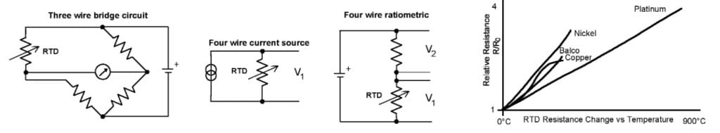
All metals change resistance when subjected to a temperature change. This temperature effect can be used as a resistance temperature detector. The RTD is the most accurate and stable type of industrial sensor. It is more linear than a T/C but still requires curve fitting. Common resistance values are 100Ω and 1000Ω for platinum, 120Ω and 500Ω for nickel, 10Ω and 100Ω for copper. Platinum and nickel RTDs are specified at 0°C, copper at 25°C. Alpha indicates the average temperature change from 0-100°C. The typical platinum industrial sensor uses the DIN α=0.00385Ω/Ω/°C, with accuracy class A (0.35°C at 100°C ) or class B (0.8°C at 100°C). The upper-temperature limit specified for platinum is 850°C. Due to its superior stability and linearity, platinum is the recommended material for most RTD applications.
Lead resistance can be a significant RTD error source, particularly for lower resistance elements. Three or four-wire sensors are used to reduce this effect. The 3 wire sensor is connected in a bridge configuration. The 4 wire sensor can be used with a current source or a ratiometric measuring circuit employing a single reference resistor.
RTDs are constructed using wire or thin-film elements. They are available in a variety of packages styles. For the typical industrial application, a stainless steel sheath is used to protect against mechanical damage and corrosion.
Thermistor
A thermistor is a thermally sensitive resistor, usually with a negative temperature coefficient (resistance decreases as temperature increases). Thermistors are manufactured from oxides of nickel, iron, manganese, copper and other metals. Of the sensor types discussed here, the thermistor is the most sensitive. It exhibits the largest change vs. temperature. Other advantages are low cost, a two-wire connection and high-level output. Disadvantages include stability and interchangeability. National and international standards for RTD and T/Cs allow interchange of sensors. However, there are no similar standards for thermistors, so interchangeability between vendors is limited. The manufacturer will usually provide a resistance/temperature curve for a particular model.
A common thermistor is a 2252Ω (at 25°C) device with an operating range of -50°C to 100°C. It is highly non-linear. Over this span the resistance changes from approximately 75kΩ to 152Ω. Other common styles are 2k, 3k, 5k and 10kΩ. Thermistors are best suited for general purpose applications with a limited temperature range, such as heating and air conditioning or food handling. Thermistor sensors are fragile and temperatures beyond the specified operating range can cause a significant loss of accuracy. Thermistors are available in beads, buttons, disks, rods, sheathed probes and other packages.
Semiconductor IC
A silicon diode junction has a well-defined voltage vs. temperature relationship (-2.25mV/°C). This characteristic is utilized in monolithic IC temperature sensors, such as the Analog Devices AD590. These devices produce an analog output proportional to absolute temperature. No curve fitting is required. Versions with either a voltage or current output are available to simplify interfacing with other equipment. High volume semiconductor fabrication techniques make this a relatively inexpensive sensor. However, the operating range is limited to <150°C and external power supply are required. One popular application of an IC temperature sensor is to determine the cold junction temperature in a thermocouple circuit.
Infrared
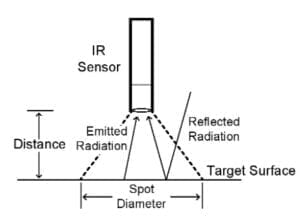 All of the sensors discussed to this point require direct contact to determine the temperature of a substance. This may not be convenient or even possible in the case of moving equipment, high voltages or hazardous environments. Infrared temperature sensors use the thermal emissions from an object to determine its surface temperature. Any object with a temperature above absolute zero radiates infrared energy which spreads at the speed of light. An infrared sensor collects this energy and produces a proportional output voltage. This can be processed and displayed by a measuring instrument.
Two parameters critical to a good IR measurement are spot size and emissivity. The sensor will measure the average temperature across its target area. Spot size is the size of the sensed area at a particular distance from the surface. It is often expressed as the ratio of distance to spot (D/S). A D/S of 4:1 indicates a 1″ diameter spot size at a distance of 4″. Working distance and spot size must be known to select the proper IR sensor.
Emissivity is a numerical value between 0 and 1 that indicates the ability of an object to emit infrared energy. Emitted + reflected energy = 1. Emissivity is determined by an object’s base material and surface finish. An ideal black body has an emissivity of 1. Shiny objects reflect IR energy from surrounding objects, thus degrading the measurement accuracy. Many IR meters are calibrated for a high emissivity (typically 0.95). A lower emissivity will cause an error in the reading. The emissivity of a surface can be increased by applying a flat paint or tape to the target area.
IR thermometers are available in a wide range of configurations, from dedicated sensors built into a process to handheld instruments for portable use. While IR measurements are not as accurate as calibrated contact measurements, their convenience and safety make them a useful technique for many situations.