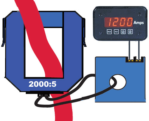
A question frequently posed to the Weschler Application team is: How to convert the output of an existing current transformer into a DC process signal? In North America, current transformers typically have a 5 amp secondary. This means the CT output is 5 amps at 60 Hz when the input is at the full rated current (e.g. 2000A to 5A for a 2000:5 CT). To convert this output to a dc signal, a small current transducer can be added to the CT secondary circuit. Products with different capabilities are available to perform this function. Here are some examples:
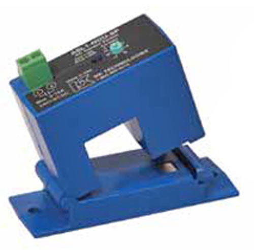 The NK Technologies AT0 offers a transducer with a 0-5A input and 4-20mA output. The split core version easily installs around the existing CT secondary wire. There is no electrical contact with the wire and this approach adds virtually no burden to the current transformer. The transducer can be located anywhere along the secondary circuit. Any previously connected secondary load, such as a panel meter, can remain in use, or it can be bypassed. This transducer is loop powered and average responding (for use on sinusoidal waveforms). The ATR0 series is similar, but true rms responding for use on distorted waveforms.
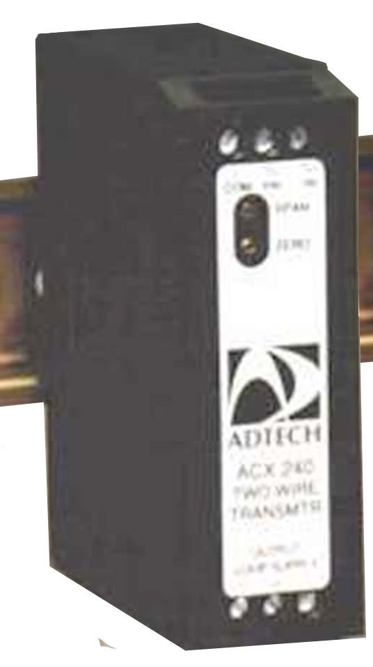 The Adtech ACX240 is DIN rail mounted transducer with a 0-1 or 0-5A input and a 4-20mA output. Response is selectable for either average or trms. A 12-42V external supply is required for this device. The CT secondary circuit must be opened to insert the ACX240. It adds up to 0.5VA burden, so the total burden, including wires to the ADX240, should be calculated. This is particularly important for smaller CTs rated at 2VA or less. Transducer accuracy is 0.25% of full scale and is field adjustable. Isolation from input to output and power supply is greater than 600V.
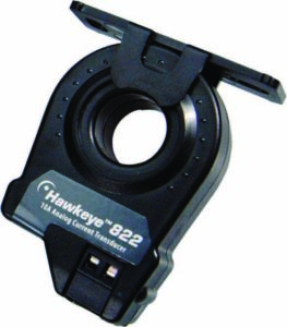 In some equipment, the maximum current in the application may be greater than the CT primary rating. In this case, the secondary current will exceed 5 amps and allowance must be made for this when selecting the transducer. Similarly, if measuring overloads is essential, then the transducer output must have sufficient headroom to track these excursions beyond ‘full scale’. In practice, this could mean picking a transducer with a 10A input. The Veris H822 is a solid core AC current transducer with 0-10A input and 0-10V DC output. A single pass of the CT secondary wire through the core allows this device to measure 2x the typical CT full scale output. If this extra margin is not needed, then two passes of the secondary through the core will provide a 10V output for a 5A input. The H822 has a 2% accuracy and is self-powered (does not require an external power supply).
Crompton Paladin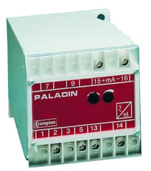 current transducers include models with 5A input and average or trms response. Either a 0-1mA or 4-20mA output can be ordered. They are Class 0.5 devices (0.5% accuracy). The input burden is specified as <2VA, so adding this device may require shorting the existing CT secondary loads. These transducers can be panel or DIN rail mounted and operate on 120V AC power. Models in the Texmate TA-1 transducer line (not shown) offer a 0-5A input with average or trms response and 0-1mA, 4-20mA or 0-10V output. These high accuracy (0.2%) transducers are powered from 115/230V AC, 24V DC or 125V DC. Burden is <0.2VA. The Yokogawa Juxta MB1 (also not shown) is a plug-in transducer specifically designed to convert a sinusoidal AC signal from a current transformer into an isolated DC process signal. It has an input burden of 0.5VA and offers numerous voltage or current output ranges with 0.5% accuracy.
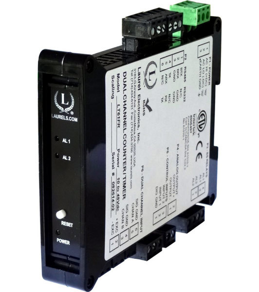 Some products perform the function of a transducer but include additional capabilities to expand the overall system performance. The Laurel LT20 family of DIN current transducers includes a 5A true rms model with 4-20mA or 0-10V output. The input resistance of 10m Ω yields a burden of 0.25VA. Digital conversion provides 1mA resolution and 0.2% full scale accuracy. This product has built-in communication via RS-232/485 or Ethernet for transmission of measurement data to a SCADA system using Modbus protocols. Two solid state relays enable the LT20 to also provide alarm and control functions. It operates from a wide range of AC and DC power supplies.
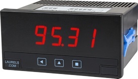 Many digital panel meters include a DC analog output for retransmitting the input signal. The universal input of the Laurel L40 includes a 5A true rms range with an accuracy of 0.5%. The 3-digit display provides a resolution of 0.01A. Input burden is 0.5VA. The isolated DC process output is 4-20mA. An optional form C relay provides alarm or control capability. More expensive DPMs are available with better resolution, accuracy, speed, and other features such as digital communication.
 Drive Capability
Another factor to consider when selecting a current transducer is its drive capability. For 4-20mA outputs, this translates to a maximum load resistance. In the products shown above, Rmax varies from 200 Ω to 900 Ω. For some devices, it is a function of the power supply voltage (e.g. 300 Ω @12V & 900 Ω @24V on the NK Technologies AT0). The drive capability on voltage outputs is characterized by the minimum load resistance. Rmin varies considerably on these products, from 500 Ω on some externally powered devices, to 100k Ω, or more, on self-powered units. These Rmin and Rmax values are generally adequate for driving an electronic device, such as a digital meter, controller, or RTU. However, they may not be sufficient to drive multiple devices or an analog meter.
Summary
In many cases, the simplest way to obtain a DC process output from a current transformer is to replace it with a similarly rated current transducer. If that is not feasible, then various products, like those shown here, can be connected to the output of the CT to obtain the desired DC milliamp or voltage signal.
More info on burden: How to Size a Current Transformer
More info on turns ratio adjustment: CT Turns Ratio and Polarity