The Current Transformer (CT) is used to sense AC current in single-phase or three-phase circuits. In the basic instrument-grade current transformer, a single primary conductor passes through the core.
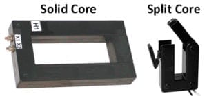
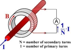 The secondary winding has multiple turns to provide a lower output current, as shown in the diagram. This allows the meter to be located away from the high current circuit. An instrumentation CT typically has a 1A or 5A AC secondary that connects to an ammeter, power meter or energy meter. CTs are available in a variety of sizes and styles, with standard ratios from 50:5 up to 4000:5. Split core models easily retrofit around existing wiring. Solid core models offer a lower cost.
Current transformers are specified by size (VA rating), ratio and accuracy. The VA rating determines the maximum secondary impedance (burden) that can be driven at the stated accuracy.
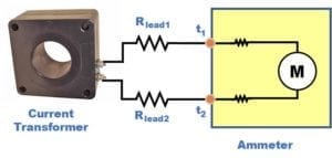 The typical transformer-rated analog ammeter has a 5A AC movement (M). Wires from the input terminals (t1 and t2) contribute a small additional series resistance. For 50 or 60Hz operation, the measurement of resistance from t1 to t2 is sufficient to determine the ammeter load. Add the two lead resistances to get the full CT burden. Some analog meters replace the 5A movement with a small internal CT and an electronic circuit that drives the movement. The same method is used to measure the ammeter load in these devices.
In many digital meters, the analog meter element (M) is replaced by a shunt resistor (typically 0.01 Ω) and an electronic measuring circuit. Some digital meters may replace the shunt resistor with an internal CT for isolation. In both cases, the measurement of meter resistance and total CT burden is the same as above.
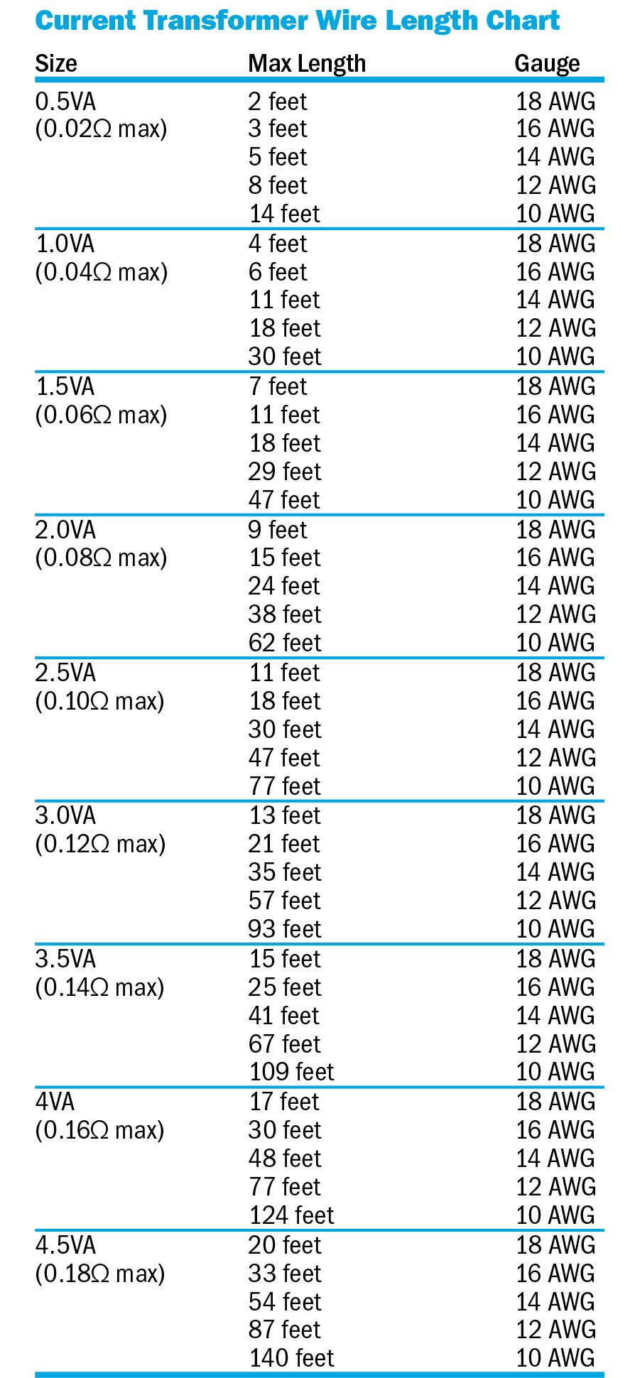
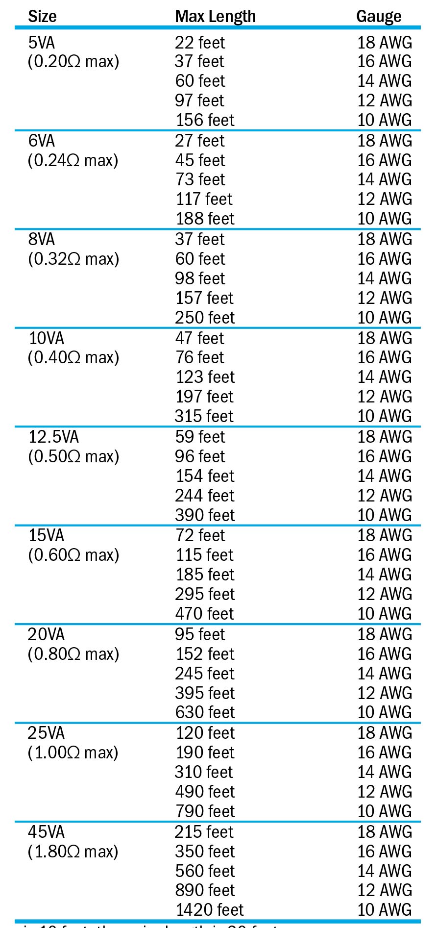
The “Current Transformer Wire Length Chart” below lists the maximum total lead wire length (Rlead1 + Rlead2) by VA rating for a CT with a 5A secondary. If the distance from the meter is 10 feet, then the total wire length for the chart is 20 feet. Values listed are based on stranded wire, 0.02Ω meter resistance and 50°C temperature. Higher temperatures will increase the lead resistance (0.4%/°C for copper). Note that the terminals on the current transformer also contribute to the CT burden, so low resistance connections are assumed.
At Weschler Instruments, we carry a wide selection of Current Transformers in both solid-core and split-core styles. Still not sure which style or ratio is right for your application?