A tachometer is an instrument that measures the rate of rotation on a gasoline engine, electric motor, disk drive, or other spinning mechanism. The reading is usually displayed as revolutions per minute (RPM) in either analog or digital format. 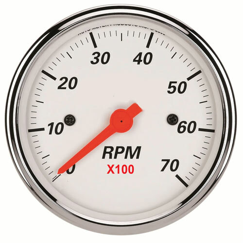 Some tachometers can also be used to measure speed or distance, with the appropriate sensor and scaling. Other common names for a tachometer are revolution counter, tach, rev-counter, RPM gauge. Most people are familiar with the tachometer in the instrument panel of their automobile. While early tachometers were mechanical, most now utilize electronics to process a sensor signal and display an RPM value.
Sensing Methods
A simple method to generate an electrical signal related to RPM is to use a switch that opens or closes as a shaft rotates. The mechanism can be designed to generate one or more contact closures per revolution. This is similar to the electrical ‘points’ in an old car that synchronized spark plug firings to engine rotation. Alignment problems, contact wear and a low RPM range are limitations of this method. Other sensing techniques overcome these limitations by eliminating direct contact with moving parts.
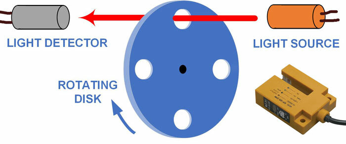 Optical sensing typically uses a light-emitting diode (LED) or laser as the source and a photo-transistor as the detector. Electrical pulses are generated as the disk rotates and the light passes through each hole. This example has 4 holes to generate 4 pulses per revolution, but any number could be employed, from one to hundreds. Notches or slots are often preferred over round holes, for a sharper signal transition. The source and detector can be mounted in one assembly, as shown in the lower right. The edge of the disk sits in the slot between the source and detector.
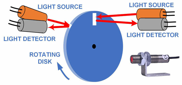 Another optical arrangement uses a reflective mark on a dark disk to return the light to the detector. On the flat side of the disk, the mark can replace a hole or notch. More typically, it is placed on the edge of the disk. As in the first example, any number of marks can be placed on or around the disk. For a disk with notches, the reflective surface is placed behind the disk, so the light reflects back to the detector when a notch lines up with a light beam. In either arrangement, the source and detector are typically mounted in the same housing to simplify installation and alignment (combined source & detector with mounting bracket shown lower right).
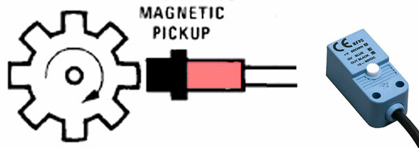 A popular non-contact sensor is a magnetic pickup or mag probe. A ferrous material (usually a gear tooth or steel stud) passing through the magnetic field at the end of the mag pickup generates a small voltage pulse. This induced voltage is proportional to the strength and rate of change of the magnetic field. Signal amplitude is therefore affected by the tooth height and the distance (air gap) between the top of the tooth and the pickup. A taller tooth and a narrower gap provide a stronger signal. If the gear stops rotating, no signal is generated, regardless of tooth position. One tooth or stud is sufficient for RPM measurement. More teeth allow quicker detection of speed changes and finer control in closed-loop systems. Two sensors mounted around the circumference of the disk are required to determine the direction of rotation.
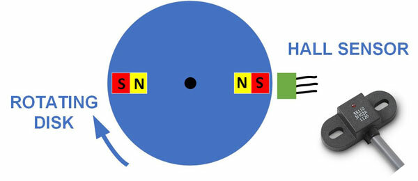 Hall effect sensors are commonly used to time the speed of wheels and shafts. A basic Hall sensor detects the presence and magnitude of a magnetic field. When a magnet mounted on a rotating disk passes the sensor, it generates an output voltage proportional to the strength of the field. Unlike inductive sensors, the output signal from a Hall sensor is not affected by the rate of change of the magnetic field. The Hall sensor will continue to output a voltage if the wheel stops with the magnet adjacent to the sensor. Some Hall sensors are mounted in a stainless-steel housing with an internal magnet and amplifier electronics, so they can be used on a ferrous-toothed wheel. These are sometimes called Hall gear tooth sensors and may look similar to an optical sensor but without the window. Two Hall sensors or a dual sensor are needed to determine the direction of rotation.
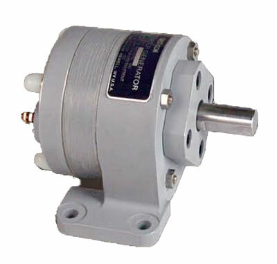 A tachometer generator is essentially the inverse of a motor. Mechanical rotation causes an electrical output voltage proportional to speed. The output polarity of a dc tach-gen indicates the direction of rotation. A tach-gen with an AC output cannot detect the direction of rotation. On these units, both the output voltage and frequency vary with speed. A voltmeter with a high input resistance should be used to measure the generator output. The Westcon tach generators cover speeds up to 40000 RPM with various housing and mounting choices.
Panel Tachometers
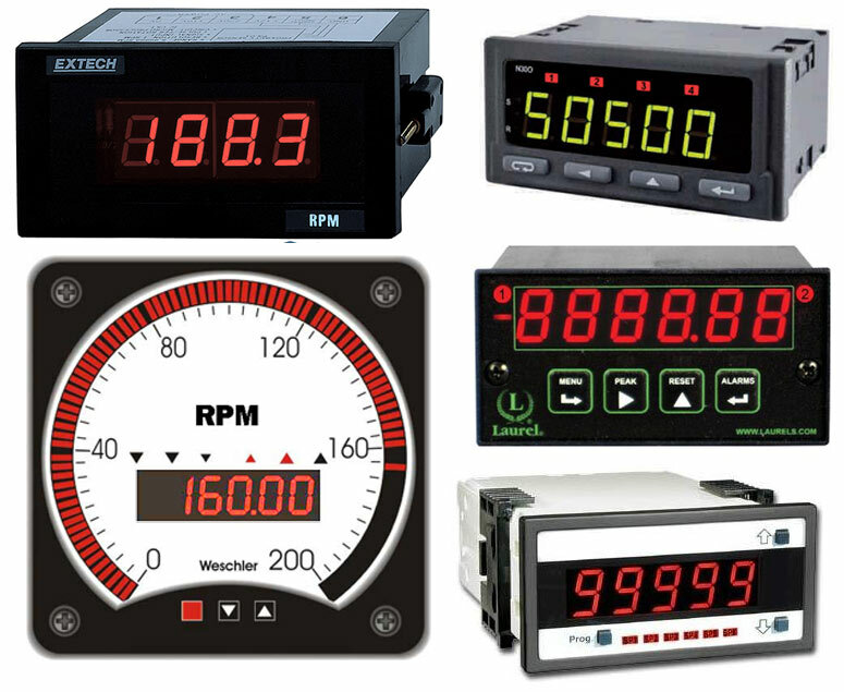 A panel meter that displays RPM can be found under several meter categories. The Extech Panel Tachometer (upper left) is a dedicated RPM meter that measures from 5 to 100k RPM and works with both magnetic and optical sensors. These can be ordered with the meter to assure compatibility. The Sifam N300 Counter (upper right) displays rotational speeds from 0.05 to 99999 RPM on 0-5V signals from sensors with integrated signal conditioning. Optional analog, RS-485, open collector and relay outputs provide system and control flexibility. The Laurel Laureate Counter (center right) is a 6 digit meter that can sense the low-level signals from magnetic pickups, as well as contact closures and the NPN or PNP transistor output of active sensors. The sensor can be powered directly by the meter, eliminating the need for an external power supply. The display in RPM or units of speed is achieved by mathematically scaling the meter for the number of pulses per revolution. The second input channel can be used with an additional sensor to determine direction of rotation. The Texmate Tiger DPM (lower right) has an RPM input module that handles mV signals from a magnetic pickup as well as PNP or NPN pulses and contact closures. Three selectable low-pass filters reduce noise. A 24V excitation output is standard.Weschler Digital Bargraph Meters (lower left) accept mag probe or logic level inputs and display RPM in both digital and bar format. The span of the single or tri-color bar can be adjusted to zoom in on a portion of the total range. Various meter sizes and styles are available. Options include an analog output, four hi/low relay outputs, serial communication, and sensor excitation.
Portable Instruments
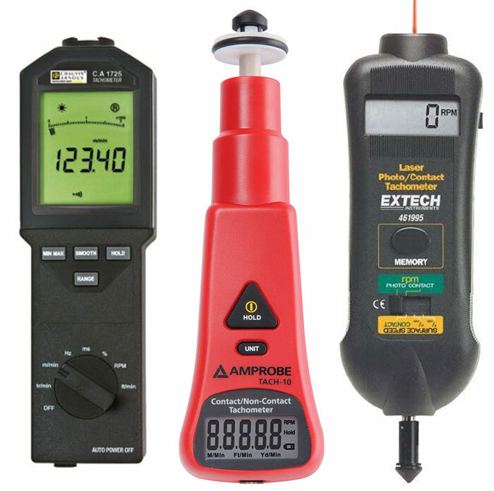 Some handheld instruments provide both contact and non-contact tachometer measurements. A wheel or fitting attaches to the meter for contact measurements. The non-contact mode is performed optically using the reflective technique. AEMC’s CA1725 Optical/Contact Tachometer (left) measures rotational speed from 6-100k RPM and linear speeds from 0.1-1000 ft/min. It also measures frequency, period, duty cycle, and counts. A calibrated wheel, conical and cylindrical end fitting and a mechanical adapter are included. USB interface and data storage are optional. The Amprobe Tach10 (center) is an economical tachometer for measuring rotational or surface speed via contact or non-contact sensing. Range is 10-100k RPM non-contact, 10-20000 RPM contact. Surface speeds of 3-30000 ft/min can also be read in m/min or yds/min. The Extech 461995 (right) provides both contact (0. 5 to 19,999 RPM) and non-contact (10 to 99,999 RPM) measurements. Laser-guided non-contact measurements can be made up to 6.5 ft. (2 m) away for added safety and convenience. The meter is supplied with wheels to measure linear surface speed (0.2 to 6560 ft/min; 0.05 to 1999.9 m/min).
Reliable and accurate speed measurements can be made for both fixed and portable applications. The sensor type and configuration, along with other application requirements, will narrow the choice of suitable products.
