Current loops are a popular method for monitoring equipment and processes in industrial environments. Some of their advantages were discussed in an earlier posting. Additional advantages of the 4-20mA loop are:
– easy detection of an open loop, since the signal zero is represented by 4mA.
– the offset zero allows use of loop-powered devices that don’t require a separate power connection.
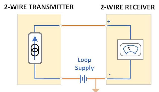
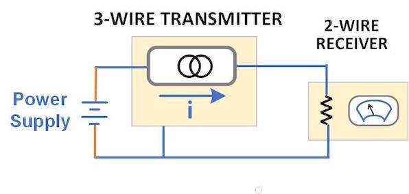
 The typical 4-20mA loop has a transmitter, receiver and power supply. The transmitter can be a sensor, transducer, signal conditioner or other measuring device. The receiver is typically a meter, recorder, controller or other monitoring device. When setting up the current loop, care must be taken to assure that the transmitter output can reach the full-scale signal level while driving the burden represented by the loop resistance. If the receiver has a current input, its resistance is internal. A receiver that measures voltage can use an external resistor across its input to monitor loop current. Transmitters with a 4-20mA output normally specify a maximum load resistance at one or more supply voltages. Receivers specify either input resistance or voltage drop across the input at full scale.
For some transmitters, a simple method to increase the drive capability is to increase the power supply voltage. A transmitter may have a maximum load resistance of 250Ω with a 12V supply. This generates a 5V output at the full-scale current. With a 24V supply, the same transmitter may specify a maximum load of 600Ω (12V out at full scale). For extremely long loops, a heavier wire will lower the loop resistance, since the wire is part of the load that the transmitter must drive. In most cases, this yields only a small improvement.
 Many transmitters require a fixed power supply voltage (usually 24V) and specify a maximum load resistance for this condition (typically 500Ω). In some cases, the transmitter may be powered from a separate ac or dc source and internally generate a dc voltage to drive the loop. It will still specify a maximum load for the loop output. For either transmitter configuration, changing the input resistance of the receiver can lower the burden. This is particularly important when attempting to add a second receiver to an existing loop. Many digital ammeters use an internal shunt resistor and voltmeter circuit to measure milliamps. Changing the meter to a higher range inserts a lower value shunt resistor. This typically results in a decade less resolution in the display. However, the lower resistance may permit both receivers to be wired in series and stay below the transmitter’s maximum total loop resistance.
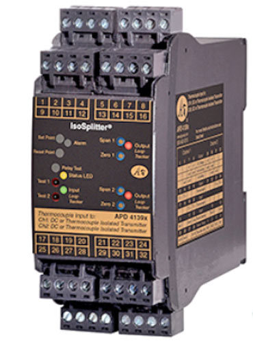
 Some loop-powered receivers have a burden of 4-8V, which is usually too high to permit using two of them in a single loop. One solution is to replace the existing receiver with a model that has a lower burden. Another method to accommodate multiple receivers is to use a transmitter with dual 4-20mA outputs, such as the API IsoSplitter family. Models are available for thermocouple, RTD, load cell, frequency and other process inputs. This solution is probably best suited for new installations.
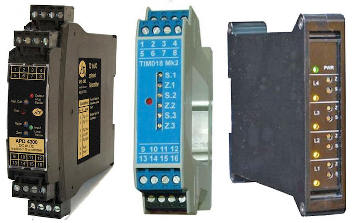
 Transmitter replacement may be impractical in existing facilities. For these situations, a loop splitter can be connected to the output of the existing transmitter. The API APD4390 (left) will split one 4-20mA signal into two identical outputs. The Weschler TIM018 (center) offers three identical outputs. The Laurel QLS (right) has four 4-20mA outputs. With a 24V supply, each QLS output can drive up to 600Ω. All three splitters have an input resistance of 50Ω (1V drop at 20mA), so they can sometimes be installed in series with the existing receiver. This is not an optimal configuration, however.
The recommended configuration for multiple receivers is a separate loop for each device. This is easy to achieve with a loop splitter. In addition to overcoming burden limitations, separate loops have the following benefits:
– Each receiver input can be referenced to ground (a receiver with floating input is not required).
– The signal to each receiver can be calibrated separately.
– If one receiver is removed or fails, the others will continue to operate.
– System troubleshooting is simplified.
This example shows the Laurel QLS splitting the 4-20mA output from a flow sensor into four signals to drive a meter, control valve, data recorder and PLC in separate loops.

A quick analysis of loop resistances and/or voltage drops will determine whether additional receivers can be added to an existing current loop. If not, there are several ways to add receivers with minor changes to the system components or configuration.
Need Help?
