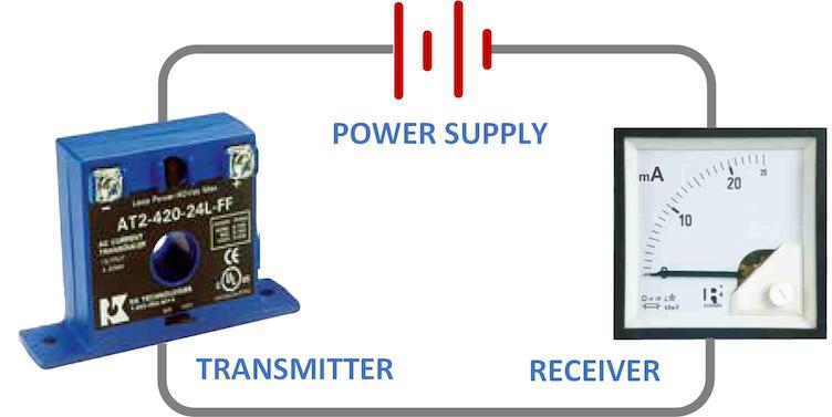
The current loop is a widely used industrial control circuit topology. The basic current loop has three elements:
- A transmitter that sends a dc current around the loop
- A receiver that measures the current in the loop
- DC voltage supply that powers the loop
Some of the advantages of a current loop for sending and receiving control signals are:
- Simple to connect and configure
- Less sensitive to background electrical noise than a voltage signal
- Can be extended over a long distance with no accuracy degradation
The primary disadvantage of the current loop is that each parameter to be measured or controlled requires a separate loop.
Standard ranges for minimum and maximum current vary by application. Popular ranges once included 0-1 mA, 10-50 mA, 0-20 mA and 4-20 mA. Today 4-20 mA is the most popular loop signal for several reasons. It requires a lower supply voltage and lower power transmitter than the 10-50 mA range. Since 4 mA represents 0, a broken loop is easier to detect than on a range where zero milliamps could be either a zero signal value or an open loop.
The transmitter in the 4-20 mA loop converts a physical parameter or electrical signal into a dc current. Common examples are pressure transducers, temperature sensors, flow transmitters, voltage converters, and current transducers. Some transmitters have a maximum output greater than 20 mA, although the accuracy above 20 mA is rarely specified.
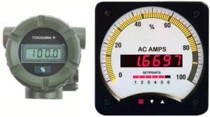
 The receiver (measuring device) is typically a meter, recorder, actuator or SCADA system. The meter may display mA directly, a percentage of full scale (with 12 mA = 50%), or the units of the original parameter (e.g. psi, °C or amps). On some digital bargraph meters, the bar can be set to indicate a percentage, while the digital readout shows the engineering units value. Certain meters will measure a signal up to 22 or 24 mA, to provide over-range capability.
The loop power supply is usually between 15 to 30 volts dc, with 24 volts the most common value. For proper operation, voltage drops around the loop at the maximum signal level must be less than the power supply voltage. Receiver burden can be specified as an input resistance or a voltage drop at full scale current. The typical voltage drop for a digital meter is 0.2-5 V at 20 mA. For some analog milliamp meters, the voltage drop at 20 mA is less than 100 mV. Wire resistance can usually be ignored since even 1000 ft of fine gauge #24 wire drops only 0.6 V at 24 mA. Voltage drops in the transmitter and receiver may be low enough to permit multiple receivers (such as a meter and a recorder) to be connected in series in one loop. After totaling transmitter and receiver drops, a 10-20% safety margin is usually added to determine the nominal power supply voltage.
If a receiver that directly measures 4-20 milliamps is not available, a series resistor can be inserted in the loop. A voltmeter is then used to monitor volt drop across that resistor. 250 ohms produces a measurement range of 1-5 volts.
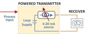
 Some transmitters include an internal voltage supply for the 4-20 mA loop. If the receiver is loop-powered (i.e. does not need an external power source to drive its circuitry), the only loop connections required are two wires from the transmitter to the receiver. Many digital meters are also able to function as a transmitter, driving a current loop output for a remote display or SCADA system input. This analog output is sometimes called a retransmit.
Since 4-20 mA current loops are so widely used in process industries, a variety of tools are available for the installation and maintenance of these circuits. Easy-to-use loop calibrators simplify setup, verification and troubleshooting. This same capability is now included in some digital multimeters.
The next posting will discuss three and four-wire loop devices and isolation issues when multiple 4-20 mA loops are used in a system.
