An instrumentation switch (or instrument switch) is a special-purpose switch used in conjunction with an electrical meter in a control panel. It allows a single meter to read multiple circuits. The most common application is monitoring three-phase ac power systems. The meter is switched into the circuit to make a measurement. For a voltmeter, this means connecting across the line. For an ammeter, to avoid switching a high current, the connection is made to a current transformer in series with each of the lines. Instrument switches are generally agency listed (e.g. UL, CSA, ETL) for wiring to mains circuits. Heavy-duty contacts assure long life.
 Voltmeter Switches
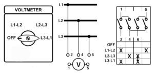
The operation of a voltmeter switch is straightforward. Non-shorting (break-before-make) contacts are used to connect the voltmeter to the main conductors. This example for a three-phase delta system shows the switch in the OFF position (meter disconnected). The next positions connect the meter from L1 to L2, then L2 to L3 and L3 to L1. The wiring to the switch is shown in the center 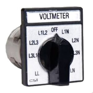 diagram. The schematic on the right identifies the closed contacts in each dial position with an X. Meter connections (terminals 1 & 5) are shown at the top. Voltmeter switches are also available for line-to-neutral measurements on three-phase Y (4-wire) systems or to measure both line-line and line-neutral voltages on 4-wire systems (see photo). Some models allow a single meter to measure phase voltages on two independent power circuits. Instrument switches are generally rated at either 240V or 600V. For higher voltages, potential transformers are used to step down the mains voltage. The switch is wired to the secondary of each transformer.
Ammeter Switches
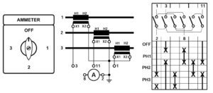
Ammeter switches connect an ammeter to current transformers (CTs) located in each phase of the mains circuit. Ammeter switches use make-before-break switching. Contacts are typically rated at 10A or more to handle popular 5A CT secondaries. Contacts rated up to 25A are available for the higher secondary currents found on some older CTs. Switches that connect to one or two CTs are used on single-phase circuits. Models for two, three or four CTs are configured for three-phase circuits. This example shows a 3-phase system with grounded CT secondaries and a grounded ammeter. In the OFF position, all three secondaries (terminals 1, 3, 11) are shorted to ground. The meter high (terminal 8) is 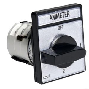 open. To get to the ‘1’ position on the dial, first the meter is connected to the phase 1 CT (terminal 3). Then ground is removed from terminal 3. The meter is now reading the phase 1 CT secondary current. To get to the ‘2’ position on the dial, terminal 3 is again grounded and the meter is connected to the phase 2 CT (terminal 11). Then the meter is disconnected from terminal 3 and terminal 11 contact to ground is opened. The meter now reads the output of the phase 2 CT. Similar action occurs going from position 2 to 3, 3 to OFF, or OFF to 3. For ungrounded transformers and ammeter, models with additional switch poles are used.
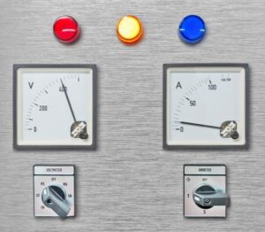 This panel includes a single analog voltmeter and a voltmeter switch to measure both phase-to-phase and phase-to-neutral voltages. The single ammeter and ammeter switch on the right are configured to measure the three phase currents. Custom switch markings have been ordered to match this system’s nomenclature. To eliminate the need to change two switches in this panel, a combined voltmeter/ammeter switch could be installed. This one switch simultaneously moves an ammeter and a voltmeter between phases. The advantage of this arrangement is that both meters always read the same phase. The disadvantage is that some measurement flexibility is lost. The typical V/A switch has 10-12 poles and is significantly longer than a single-function instrument switch.
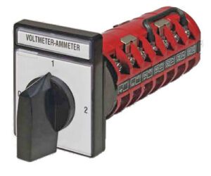 At one-time instrument switches were common in switchboard power panels. Digital meters that display multiple parameters have reduced the demand for these products. The remaining needs are still filled by multiple suppliers. In addition to the replacement of existing switches, instrument switches are used in new applications when panel space is limited. Also, some users prefer the clean look and reduced confusion of fewer readouts, but with the flexibility to occasionally view each phase when needed.
