Flow is an essential measurement in many industrial processes. In the typical application, a flow sensor is used to determine the volume of liquid or gas that passes thru a pipe, in liters/sec, GPM or similar units. Modern sensors incorporate electronics that can correct for varying pressure, temperature, density, non-linearities, and the characteristics of the fluid. These sensors may provide a local readout but usually will also send a signal to a remote indicator or SCADA system. Electronic sensors don’t measure flow directly. They rely on another sensing method to infer the flow rate. Popular types of electronic flow sensors are differential pressure, thermal, target, paddle wheel, and magneto-inductive.
Differential Pressure Flow Sensors
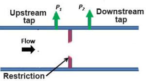 Differential pressure flow sensors are the most popular type due to their cost, performance, and versatility. These sensors have a flow body of known cross-section, that includes a built-in restriction, such as an orifice plate. The restriction creates a difference between the upstream and downstream pressure. The sensor detects this difference to calculate the fluid velocity and determine the flow rate. This technique has no moving parts and is suitable for a wide arrange of liquid and gas media. Careful placement is necessary to avoid turbulent flow. An alternate construction uses a Venturi nozzle as the restriction. The downstream pressure tap is placed in the nozzle. The flowing medium generates a pressure difference proportional to the flow rate. However, the pressure drop is substantially less than with an orifice plate. The Venturi method is preferred for higher flow rates or low pressures.
Thermal Flow Sensors
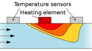 Thermal (calorimetric) flow sensors measure heat conduction in a liquid or gas to determine flow rate. The temperature is measured upstream and downstream of a heating element. At zero flow, the temperatures are equal. As flow increases, more heat will be detected at the downstream sensor. This method is particularly useful at low flow rates. At higher rates, the amount of power supplied to the heater is varied to maintain a fixed temperature difference between the two sensors. The power level is converted to flow rate by the internal electronics. In a further refinement of the thermal flow technique, a single element is used to both heat the probe and measure temperature. The heat input and amount of heat dissipated in the fluid are used to determine the flow. Thermal flow sensors have no pressure drop.
Target Type Flow Sensors
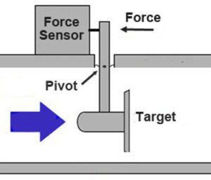 In a target type flow sensor, a target plate is placed in the liquid stream. Fluid flow exerts a force on the target, which moves in relation to flow rate. This is measured with a force sensor at the other end of the lever arm. In an alternate technique, the lever arm works against a spring. The movement of the arm is measured with a position sensor to determine flow rate. A permanent magnet attached to the lever arm and a Hall effect sensor are often used to convert the angular motion of the arm into an electrical signal. Target-type sensors offer a very low-pressure drop and generally tolerate fluids with that contain some solids.
Turbine Flow Sensor
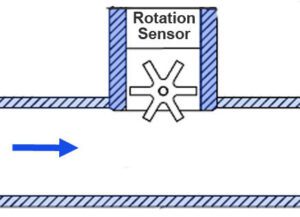 The paddle wheel or turbine method places a spinning part in the fluid to detect flow. The fluid is first routed through a laminar flow element to eliminate turbulence. It is then directed to the wheel or turbine, which revolves in proportion to flow rate. A magnet on the wheel and magnetic detector in the housing are typically used to measure rotation. An optical detector may be employed in sensors for use with clear fluids. The paddle wheel is useful for low flow liquids (GPH), the turbine for the lower density of gases. Both have more wear than other methods due to the spinning part. These sensors are low-cost and straightforward to install.
Magnetic Induction Flow Sensor
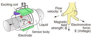 The magneto-inductive technique is used to measure the flow of conductive liquids. According to Faraday’s law of magnetic induction, current is induced into a conductor as it moves through a magnetic field. The amount of current induced is directly proportional to the velocity of the moving conductor. A conductive liquid passing through the flow sensor body acts as the conductor. The sensor contains a set of coils that generate the magnetic field. Electrodes mounted in the sensor body conduct the current. Current magnitude is proportional to flow rate. This type of sensor has no pressure drop and no moving parts. It is not affected by changes in temperature, pressure, or density and can handle fluids with contaminants.
Sizing & Configuration
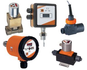 Each sensor type is available in a variety of sizes and mechanical configurations, with or without a local display. This photo shows Kobold flow sensors that use the sensing methods just described (clockwise from the left: differential pressure, target, paddle wheel, magneto-inductive, and thermal). The sensing method usually can’t be determined by a sensor’s physical appearance.
Most sensors convert the flow into process output signal of 4-20mA, 0-10Vdc, 0-5Vdc, pulse or frequency. A switch output can often be added to control external equipment based on a flow setpoint.
Selection of the flow sensor type will depend on the fluid characteristics, flow rate, pressure, temperature, pipe size, acceptable pressure drop, and cost; plus ease of installation and maintenance. Consult the manufacturer’s technical data for recommended models and application guidance.
