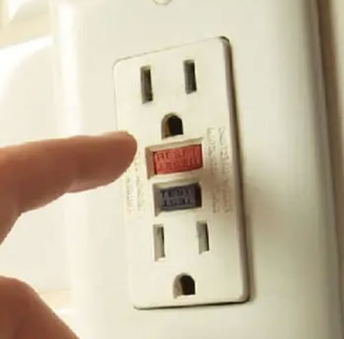
In residential applications, ground fault sensing is used to protect a building’s occupants from electric shock. Everyone is familiar with the ground fault interrupter (GFI), incorporated into a duplex outlet, that quickly opens the circuit when a fault is detected. The National Electric Code mandates their use in kitchens, bathrooms and other wet locations. To provide a high degree of protection in these areas, the trip limit is set at 6mA by national safety standards. While operator safety is important in industrial settings, ground fault sensing is also used there, with different limits, to protect equipment from damage.
 Under normal conditions, current flows from the power source to the load and back to the source. As a result, the electromagnetic fields surrounding the conductors are equal and opposite. When a current leaks to ground (fault condition), the conductor currents become unbalanced and a magnetic field is produced.
The ground fault sensor detects this field and provides a proportional output signal. A ground fault relay trips alarm contacts (either open or closed) when the leakage rises above the setpoint value. This alarm contact can be used to open a circuit powering a contactor or activate a shunt trip circuit breaker. In many industrial processes, however, the sudden shutdown of key equipment can be destructive to the process or the equipment. For these situations, a visual, audible or electronic alarm may be preferred rather than an automatic trip. This notifies the operator that a fault has occurred and needs attention, but allows the process to continue to completion.
The 6ma trip limit is effective where bare feet on a wet floor provide a low impedance path the earth. These conditions are not expected in industrial settings. A higher limit can provide sufficient operator protection while reducing spurious tripping caused by leakage through motor windings, or capacitive coupling in long cable runs. Limits of 30mA, or even higher, are common in industrial systems. Large motors and overhead cranes often exhibit higher leakages, particularly on damp days.
AC Systems
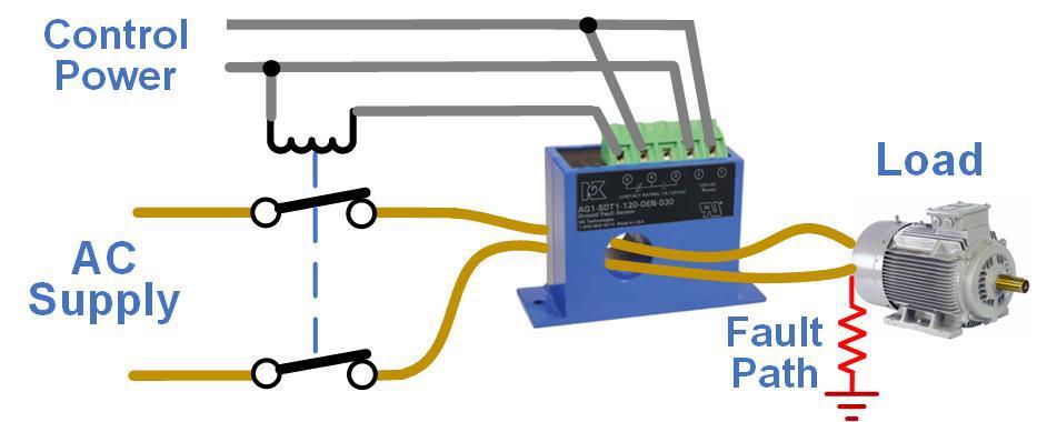
 To monitor loads operating from single-phase AC power, the line and neutral wires are routed through the core of the ground fault relay. A contactor is typically used to interrupt the supply when the fault current exceeds the setpoint value. In this diagram, the contact inside the ground fault relay closes to activate the contactor coil and open its normally closed contacts. A separate power source is used to run the ground fault relay and contactor. Note that all current-carrying conductors must pass through the sensing aperture, including the neutral if the load uses one.
When the sensor is placed close to the source, it will detect leakage in downstream wiring as well as the load. When the sensor is placed close to the load, any leakage in wiring before the sensor will not be detected. A system designer may specify one sensor to monitor several loads. While cost-effective, leakages in the loads are additive, so the sensor will detect a higher overall leakage level. This arrangement also makes it difficult to isolate the source of a fault.
In three-phase delta systems, all three supply wires must be routed through the core of a single ground fault sensor. It will detect an imbalance in the vector sum of the feeding circuit phase angles, which equates to a fault current. For three-phase Y systems, the phase wires and neutral wire are run through the core. If the system has a grounded neutral, passing only this conductor through the sensor will provide the same result.
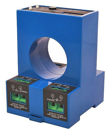
 The NK Technology AG Series is a popular line of industrial AC ground fault relays. The trip point is 5/10/30mA (jumper selectable) or it can be factory set to any value from 5 to 950mA. Automatic reset models with form C (changeover) contacts and latching models with form A (normally de-energized) or form B (normally energized) contacts are available. Control power can be 120VAC, 24VAC or 24VDC. For higher power loads or to monitor multiple loads, their AGLD Series (shown here) has a 1.8” (46mm) aperture.
Ground fault detection usually results in a trip or alarm action when a fault occurs. In some cases, it may be useful to continuously monitor the health of the system by tracking the magnitude of the leakage current. A low-level fault can increase over time until it becomes a hazard to the operator or equipment. The NK’s AGT Series are loop-powered ground fault transducers with either a 50mA or 100mA input range and a 4-20mA output. This output can be sent to a panel meter with setpoint relays to display the reading and alarm on degraded performance before a trip level is reached. As an example, if the trip level is 100mA, the alarm points in the meter can be configured so one alarm is initiated when the fault current reaches 30mA, and another at 70mA.
DC Systems
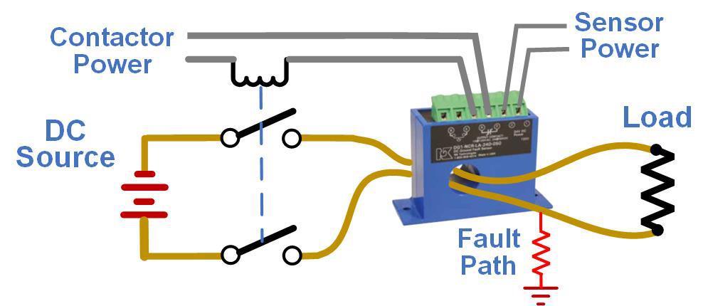
With the proliferation of photovoltaic panels and backup power supplies, the need for ground fault detection in DC-powered systems is increasing. In solar panels or battery-operated devices, wet connections can compromise isolation and cause current flow to ground. Deteriorating insulation can also provide a ground current path. A DC ground fault relay will detect this current and activate a relay to disconnect the power source. This protects the machinery and keeps operators safe from accidental shocks. It can also be used to generate an alarm rather than initiate a shutdown.
 The DG Series Ground Fault Relay from NK Technologies has internal contacts that change state at a fixed point, which is factory set between 5 and 50mADC. The one-piece, solid-core design allows for installation on wires feeding loads to about 50A. 24VDC is required for sensor power but contactor power can be 24VDC, 24VAC or 120VAC. This diagram shows a unit configured for fail-safe operation. The contactor is normally open. Both sensor power and contactor power are needed for the sensor to energize the contactor coil and complete the circuit to the load. When the sensor detects a fault, it de-energizes the internal relay and opens the circuit to the contactor coil. The output can be automatically reset or latched.
Summary
In industrial settings, ground fault sensing provides both operator protection and equipment protection. System designers must consider multiple requirements when selecting and configuring protection devices. Fault thresholds and actions are determined by the process being monitored, the equipment condition, and the type of access provided to operating and service personnel. A variety of products are available to meet the increasing demand for industrial ground fault protection.
