An instrumentation Current Transformer (CT) is used to step down AC current to a level that can be more easily measured by a panel meter or test instrument. The amount of step down is specified by the CT ratio (e.g. 300:5).
The formula for the CT ratio is:
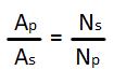
Where
Ap = Primary amps
As = Secondary amps
Np = Number of primary turns
Ns = Number of secondary turns
Using this formula, a 300:5 current transformer with one primary turn has 60 secondary turns. These are usually wound with fine-gauge wire and hidden inside the CT housing.
The nameplate CT ratio assumes that the primary conductor passes once through the center window. Each pass of the primary conductor through the window is counted as one primary turn. Large changes in ratio can be achieved by running the conductor through the window more than once. A 300:5 CT with two passes (turns) becomes a 150:5 CT. Three passes yield a 100:5 CT.
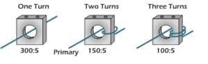
One reason to do this is that a higher ratio CT generally has better performance than a low ratio CT. The accuracy and burden characteristics of a CT are not changed by using multiple primary turns. However, the window must be large enough to accommodate the additional turns of heavy gauge primary wire.
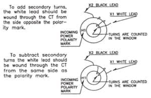
Smaller ratio changes can be made by using additive or subtractive turns on the secondary. On a CT with one primary turn and a 5 amp secondary, each secondary turn modifies the ratio by 5 amps. One turn additive on a 100:5 CT becomes a 105:5 CT. One turn subtractive becomes a 95:5 CT. An additive turn is wound by running the X1 lead through the window from the H2 to the H1 direction (from the side opposite the polarity mark). A subtractive turn runs the opposite direction (from the side with the polarity mark).
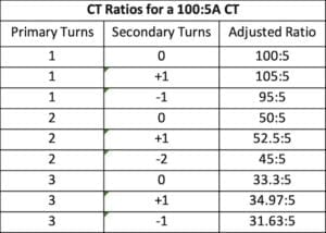
Adjusting both primary and secondary turns provides additional ratios for a specific current transformer. A few examples for a 100:5 transformer:
Observing CT polarity is important when adding or subtracting secondary turns. CTs are manufactured to produce a secondary current that is in phase with the primary current when installed with the correct orientation. The relative polarities of CT primary and secondary terminals are identified either by painted polarity marks or by the symbols “H1” and “H2” for the primary terminals and “X1” and “X2” for the secondary terminals. The convention is that, when the primary current enters the H1 terminal, secondary current leaves the X1 terminal.
Correct CT polarity is also required when using multiple current transformers to make three-phase measurements. By convention, the H1 side (or polarity dot) of each CT is oriented toward the source, the H2 side toward the load. Incorrect orientation of either the primary or secondary on one or more CTs may give incorrect current and/or power readings.
Warning: Current transformers step down the current but step up the voltage. An open secondary loop on a 1A or 5A CT can produce hazardous high voltage.
For additional CT information please visit our How to Size a Current Transformer blog.