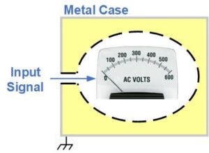
Isolating the measuring instrument from other circuits and earth is a simple task when using an analog meter. Most analog meters have two terminals to connect the input and no other circuit connections. The plastic case provides an insulation barrier to the metal panel or cabinet, which is tied to earth for safety. If the meter has a metal case, then an internal barrier isolates the meter elements from the case and the panel. The amount of isolation is often specified as Dielectric Withstand, with typical values of 1000, 1500 or 2300V at 50/60Hz. Resistance from input to case may not be specified, but typically exceeds 100MΩ.
 Digital meters usually require external power, so isolation is a more complex issue. If the power source and input signal share a return line, there is no isolation between these circuits (left diagram). This is often the case when the meter is operated from a DC supply. A meter with a differential input and a non-isolated supply may tolerate a small difference between input low and power supply low. The amount is dependent on power supply voltage and the meter’s internal circuits. For other power sources (for example, mains power), the power supply in the meter provides isolation. This is usually achieved with a 50/60Hz mains transformer or a high-frequency transformer that is part of an isolating AC or DC input switching supply (right diagram).
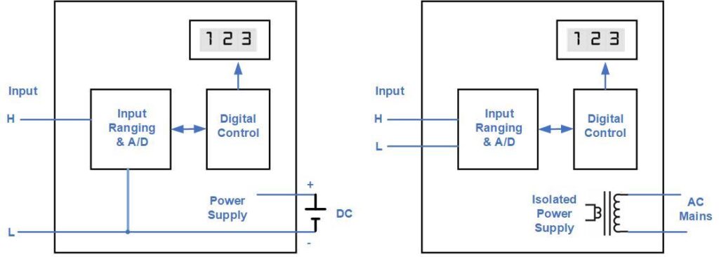
Most digital panel meters are housed in a plastic case. The case provides an insulation barrier to a metal panel. For meters with a metal case, an internal insulation barrier is required, as shown for the analog meter. The isolation between Input H/L and chassis or earth is sometimes referred to as maximum common mode voltage.
Many meters include electro-mechanical relays for control outputs. The relays provide electrical isolation from coil to contact on the relay and from one relay’s contacts to all other contacts (channel to channel). Relays used for this purpose typically have dielectric isolation greater than 1000V at 60Hz. This allows multiple relays to be powered from the supply that operates the digital circuits in the meter. One caution, however: the capacitance between contacts and coil provides a path for high-frequency signals and fast transients to couple from the relay contacts back into the meter. This could cause erratic meter operation. MOVs and other components used to protect relay contacts reduce this problem.
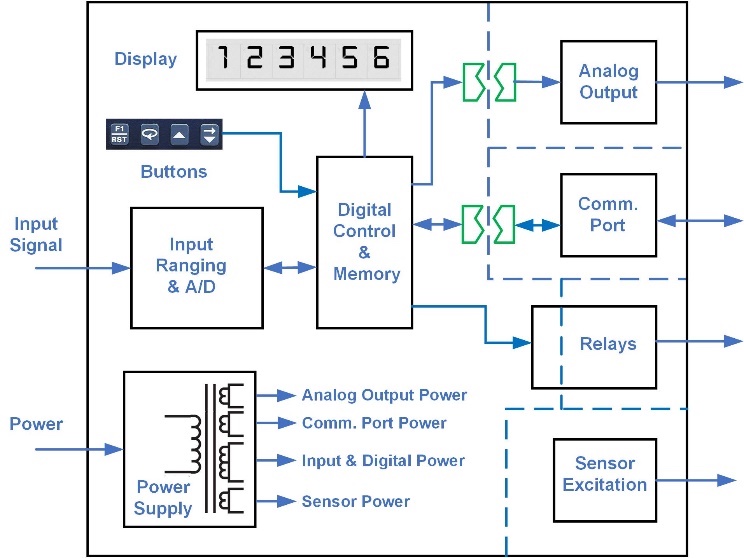 Some panel meters have signal outputs for remote monitoring, communication, or control. In the simplest implementation, the output low is connected to the circuit low inside the meter. Depending on how the meter is connected in the application, this can lead to ground loops, malfunctions, or equipment damage. A more robust meter isolates each output, giving the user more flexibility in connecting, and more reliability in operating, the meter. The block diagram of an advanced meter shows this configuration. The dashed lines indicate isolation barriers. The analog output, digital communications, and sensor excitation outputs are separated from the input, power source and other outputs by isolators on signal lines and separate windings on the transformer. Another method used by meter manufacturers for power supply isolation is to use one isolating AC to DC converter driving a number of small, isolating DC to DC converters.
In meter specifications, there is no standard term or format for isolation. It may be listed as dielectric withstand, dielectric strength, insulation resistance at a DC voltage, or simply isolation. It may be shown separately for each input and output, or combined into one comprehensive spec. One voltmeter’s specification for the analog out, power and relay connections is:
Isolation: 250V rms working, 2.3 kV rms per 1 min test.
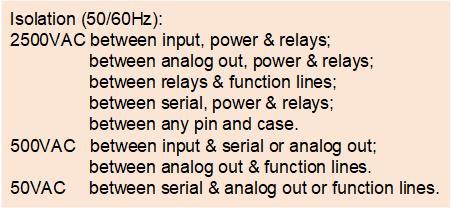 This means the meter will withstand 2.3kV between the analog output terminals and all other terminals, between the power terminals and all other terminals, between relay contacts and all other terminals. Working voltage is significantly less, to allow for voltage spikes, insulation aging, dirt accumulation, and other factors. A fully specified meter (see shaded box) includes withstanding voltage for each port to every other port.
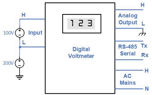 In this application example, the meter is set to measure a 100VDC input floating 200V off earth. For safety, the meter isolates the mains supply from inputs and outputs. The 0-5VDC analog output drives an instrument that has low connected to chassis and eventually earth. The meter must isolate this output from the input to allow the floating measurement. The RS-485 port must also be isolated from the input. The Tx and Rx lines typically connect to a computer network and operate within a few volts of system ground. While resistors can be used to reduce circulating current in ground connections, a more robust method is to provide an isolated supply for the serial port. This tolerates larger ground offsets and improves noise margin.
Meters with multiple inputs that don’t share a common low should specify the maximum voltage allowed between the inputs. A typical example is a dual-channel meter that has a differential input on both channels. The maximum voltage between channels could be a few volts or a few hundred volts, depending on the meter’s internal architecture. Another example is an AC power meter, which has voltage input(s) and current input(s). Many manufacturers include an internal transformer on each input to isolate it from the other inputs and internal meter circuitry.
Multiple analog outputs may have individually isolated signal lines but share a power supply. This provides input-to-output isolation, but limited or no channel-to-channel isolation. A shared supply may be sufficient when the outputs connect to the same external device, such as a data logger. Where the channels go to different locations, a voltage differential could exist between the low terminals in the system. Complete channel-to-channel isolation, including an isolated supply for each output, will tolerate this voltage difference.
These are a few of the isolation issues when using a panel meter in a measurement or control system. System performance problems, caused by unintended connections or limited isolation inside a meter, can be difficult to troubleshoot. Examination of the meter specifications, operating instructions and system diagram will help assess whether it has sufficient voltage isolation for the intended application.
