Many digital panel meters include electro-mechanical relay outputs to control external devices. Protecting relay contacts from excessive voltage and current is important to achieving the long operating life that digital instrumentation is designed to provide.
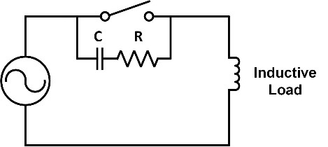 Motors, contactors and actuators typically are inductive loads. Arcing occurs as the relay contacts open due to the energy stored in the load’s magnetic field. A capacitor across the contacts suppresses the voltage spike and reduces the surge current through the contacts. A resistor in series with the capacitor limits the capacitor current the next time the contacts close. The RC circuit can also reduce contact degradation due to contact bounce and chatter. The resistor and capacitor are often purchased as a single two-wire device, called a snubber. The correct value of R and C depend on the characteristics of the load and associated wiring. Snubber manufacturers offer formulas for estimating the values, but caution that the final values should be determined by testing. Incorrect component values can actually shorten the relay life. Since meter manufacturers design their equipment for a wide range of applications, they generally do not include snubbers inside the meter. This type of protection must be implemented by the user. Note that the RC network across the relay contacts will cause a small leakage current in AC circuits when the relay is open. If this is a problem in the application, the RC circuit can be placed directly across the load. This has the added benefit of limiting surge current in the supply leads, which may reduce EMI.
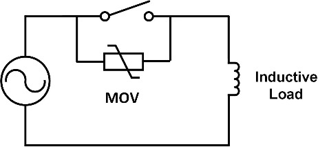 A metal oxide varistor (MOV) is another component that can be used to protect relay contacts. A popular application for this device is in surge protectors used with home computer equipment. The MOV has a high resistance below its operating voltage and a significantly lower resistance above that voltage. The MOV is used to limit the voltage across relay contacts as they open and dissipate some of the energy from the current surge. MOV selection is based on breakdown voltage and Joule rating. The MOV value is less dependent on load characteristics than the RC circuit. Therefore, this device may be added by the user or included by the meter manufacturer. A second MOV can be placed in parallel with an existing MOV for added energy absorbing capacity. A MOV can also be placed directly across the load, either instead of or in addition to, one across the contacts.
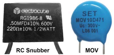 Pictured here are a typical snubber and MOV. The snubber has insulated wire leads that can be directly connected to terminal strips or wired into a circuit using wire nuts. Small MOVs have bare wire leads for easy PC board mounting. Larger sizes may have spade terminals.
Relay contacts in DC circuits experience more contact wear during switching since there are no zero voltage crossings to help extinguish the arcing that occurs with inductive loads. A typical PC mounted relay used in a panel meter might be rated in an AC circuit for 10A@250V with resistive loads and 1/2HP@250V on motor loads, but in a DC circuit, it can switch only 6A@30V with resistive loads. Therefore, the protection level and component values will change for DC applications. Protection method may also change.
Using only a capacitor across the relay contacts is not recommended. It would decrease arcing when the contacts open. However, the energy stored in the capacitor quickly dissipates as a high (short circuit) current when the contacts close. This results in excessive contact wear and often a shorter relay life than without a capacitor. Recommended methods for contact protection in DC circuits include both RC snubbers and MOVs, as described above. Location can be either across the load or across the contacts.
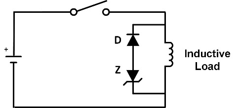 Another method frequently used in DC circuits with inductive loads is a reverse-biased diode-connected directly across the load. When the relay contacts open, the energy stored in the inductive load flows through the diode and is dissipated back in the load. No voltage spike appears across the switching contacts and arcing energy is reduced. However, the load turn-off is delayed since current continues to flow after the relay contacts open. If this is a problem in an application, the delay can be reduced by adding a Zener diode in series with the diode. The combination limits the voltage across the opening contacts while shortening the duration of the circulating current.
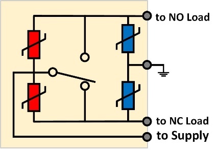 Many applications, such as resistive loads, small inductive loads or low energy circuits, don’t require protection of the panel meter relay outputs. Other applications require knowledge of the load characteristics to properly configure the output protection. Therefore, in most general-purpose panel meters, protection of relay outputs is left to the user. Specialized meters, designed for specific applications where the load characteristics are known, may include contact protection. If the meter has a connection for earth ground, a high level of protection is achieved by adding MOVs across the contacts and from contacts to earth. For a form C relay, this requires 4 MOVs per relay. Protection components in a meter can affect leakage, hipot and surge testing on those outputs. Hipot testing with the current limit set too high may even damage the meter. A discolored or cracked case indicates an overloaded (failed) MOV.
The general methods shown here can also be employed to protect the solid-state relays used in some meter outputs. While semiconductor devices aren’t limited by contact wear, they can be more susceptible than mechanical relays to failure from transients and surges.
Weschler Instruments Applicable Product Offerings
Panel meters with relay outputs are available from Weschler Instruments under many sub-categories, including Bargraph Meters, Controllers, Digital Panel Meters, Meter Relays, Process Meters, and Temperature Meters.