A meter relay is a meter with a switched output that can be used to control a process or activate an alarm. In its simplest form, an analog meter relay uses mechanical contacts or a microswitch to operate an external device when the analog meter pointer reaches the level of the set pointer. Today’s analog meter relay has solid-state circuitry and a relay in place of a mechanical switch. Three popular case styles are shown here: panel (left), DIN (center) and ANSI switchboard (right). Two methods for sensing the signal level are commonly available: optical sensing and electronic sensing.
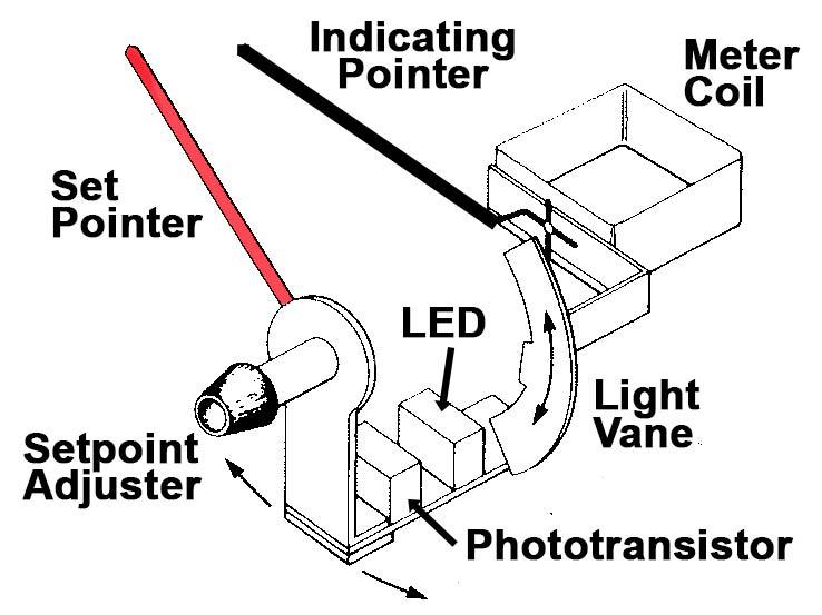
 In an optical meter relay, the input signal drives an analog meter. The meter coil moves an indicating pointer in proportion to the signal magnitude. An adjustment knob or screw changes the position of the set pointer. The infra-red source (LED) and phototransistor are mounted directly on the set pointer mechanism. The entire mechanism rotates when the setpoint is adjusted. A vane attached to the moving coil of the analog meter interrupts the LED beam as the indicating pointer moves past the set pointer. This interruption changes the state of a phototransistor, which switches an electronic circuit that either energizes or de-energizes the output relay. As long as the indicating pointer remains above the set pointer, the light is blocked and the output stays switched. For meter relays with high and low setpoints, a second set pointer mechanism, moving vane and electronic circuit change the state of the low limit relay when the indicator is below the low setpoint. The electronic circuit may include normal or fail-safe operation provisions, delayed actuation (time delay), latching relay action (with pushbutton, external or power-down reset), and delayed latching. Optical sensing provides a setpoint value that is not affected by contact pressure on the indicating pointer. It also switches rapidly, with a narrow deadband. The focused infra-red beam is immune to ambient light. Since the meter has no digital circuits, it doesn’t generate electromagnetic interference.
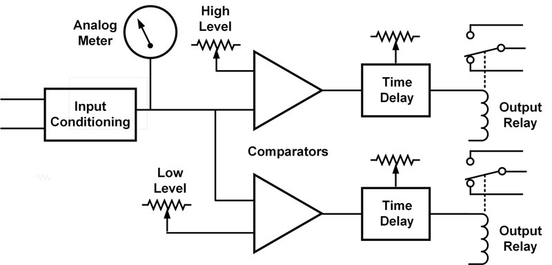
 With electronic sensing, the input signal is not directly connected to the meter movement. An input circuit conditions the signal to drive both the analog meter and setpoint comparator(s). The setpoint level potentiometer changes the reference signal to the comparator and mechanically moves the set pointer visible on the meter face. When the signal voltage exceeds the setpoint voltage, the comparator switches. The comparator output may operate the relay directly or feed an additional circuit that modifies the relay drive signal. One popular modification is the introduction of a time delay to prevent relay chatter, false alarms or excessive output cycling. Relay operation can be normal, fail-safe, latching, etc. The input conditioning block provides a higher input impedance than the optical sensing method, so there is less load on the input signal. Input conditioning can also be used to amplify low-level signals, convert non-linear inputs, or drive sensors that require excitation (e.g. RTD or strain gauge). One manufacturer offers an option to add proportional control in the comparator stage. In this mode, the meter relay will vary the output duty cycle to tightly maintain a set input level, such as an oven temperature.
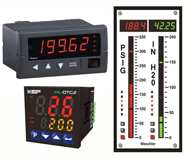
 With electronic sensing, the analog meter movement can easily be replaced with a digital display. Many digital panel meters offer optional relay outputs, so they can be used as digital meter relays. Digital controllers, smart meters, and thermostats are other digital products that often include relay outputs. Three types of digital displays are shown here. Upper left is a meter with relay output that has a single display. Setpoint values are viewed via the front panel buttons. Lower left is a meter relay that displays setpoint value in a second digital display. Right is a dual digital bargraph meter that shows the magnitude of each input signal in both the digital display and bar display. The high and low setpoint values are indicated in each bar by a lit segment if the signal is below the setpoint, and an unlit segment if the signal is above the setpoint. Tri-color bargraph meters can be programmed to change the entire bar color when the input passes a setpoint for increased visibility.
In most digital meter relays, the analog comparators are replaced by digital circuitry and a microprocessor. The micro also controls the analog to digital converter and digital display. Setpoint values are entered using setup menus and front panel buttons, rather than with a potentiometer. Digital meter relays often have additional programmable parameters such as digital filtering, hysteresis, trigger delay, and curve fitting. Other benefits of a digital meter (such as higher accuracy, better resolution, network communications) are also available in digital meter relays.
One element common to both analog and digital meter relays is the output relay, which can be either a mechanical or solid-state device. Relays typically have a form A (normally open) or form C (normally open and normally closed) contact configuration. Form C is also called double throw or changeover. The block diagram shows two mechanical relays with single pole, form C contacts. A mechanical relay isolates the output circuit from the input, meter power supply and other outputs. Typical isolation is 500 to 1500 VAC.
A key factor in the utilization of mechanical relays is contact life. Current surges, back emf and arcing can quickly degrade contacts and reduce operating life. The highest switching current is specified for AC resistive loads, with deratings for inductive, capacitive and DC switching. Various protection schemes (such as an RC network across the relays contacts) can be used to limit switching transients. Careful selection of component values is important since incorrect values can shorten contact life, rather than improve it. Solid state relays are not subject to contact wear or mechanical life limits. However, they still may need protection from overvoltage, overcurrent and transients. On-state voltage drop and off-state leakage can be problematic in some applications. Isolation of the switched circuit from other circuits may not be as high as mechanical relays provide.
A variety of analog and digital meter relays are available to perform today’s control applications. Selecting the right model involves matching the meter’s capabilities to the application’s requirements. The selection tool on the Weschler website allows users to quickly sort the available products by 7 parameters: type, size, input, # setpoints, power, communications, and manufacturer.
