Specifications for panel meters and test instrumentation usually include an accuracy value. This number defines the maximum amount the meter reading or transmitter output will differ from the ideal value, as determined by an established reference standard. Accuracy is usually expressed as either a percent of reading or a percent of range.
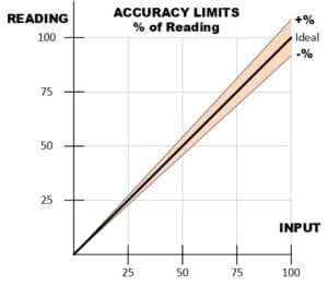
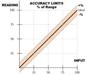
When accuracy is expressed as a percent of reading, the allowed error decreases as the input level decreases. For accuracy as a percent of range, the allowed error is a constant, regardless of input level.
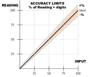 Many products combine the two methods to allow for some additional error at low signal levels. In a digital meter, the fixed amount can be a number of display counts (least significant digits), a numeric value in the units being measured (e.g. volts or amps), or a percent of range.
Examples of the three formats:
± (0.1% of reading + 2 digits)
±(0.1% of rdg + 10 μV)
±(0.1% of reading + 0.01% of range)
This graph shows the expanded error band due to the additional term.
A few counts of additional error on a 10,000 count digital meter may seem insignificant. At low signal levels, however, it is a larger factor than the percent of reading. This meter, with a specified accuracy of ±(0.1% of reading + 2 digits) on the 10 volt range, has an error at 1 V of ±(0.001 V + 0.002 V) = ±0.003 V or 0.3% of the input level.
Analog meters usually specify accuracy as a percent of range, so operation near full scale is important for accurate readings. A meter that is 1% of range is also 1% of reading at full scale, but only 10% of reading at an input of 1/10th full scale.
Specialty meters sometimes state accuracy as a fixed amount, rather than a percentage. Temperature meters and transducers often use this format. The accuracy specification may be broken into bands to define how well the meter conforms to the RTD or thermocouple reference curves/equations. An example for a Type T thermocouple:
0°C to +400°C Accuracy ±0.03°C
-275°C to 0°C Accuracy ±0.2°C
For any meter or transducer, the specified accuracy is valid at a certain ambient temperature, such as 25°C or 18-28°C. At other operating temperatures, an additional error for temperature coefficient (TC) applies. This term is usually stated as a %/°C and can be a significant factor. For example, a 0.01% of reading accuracy at 25°C with a TC of 0.0005%°C, becomes an 0.0175% of reading accuracy at 40°C.
Humidity is another factor that can affect accuracy. Many digital products specify a maximum relative humidity, such as <90% RH at 40°C. Non-condensing is also typically specified since moisture on the surface of circuits can degrade performance.
Transducers and high accuracy meters may include a linearity specification. In process equipment, this defines the maximum deviation from a straight line between zero and the actual full-scale point. It is a lower (i.e. better) value than the accuracy specification since it doesn’t include any calibration error. Linearity is more useful than overall accuracy when making a relative measurement between two values of an input.
In analog meters, position can affect meter accuracy. If the meter is calibrated for vertical operation, the Position Influence specifies the accuracy degradation if operated horizontally. Magnetic fields may affect the analog mechanism, so some meters include shielding or a derating for operation in strong fields.
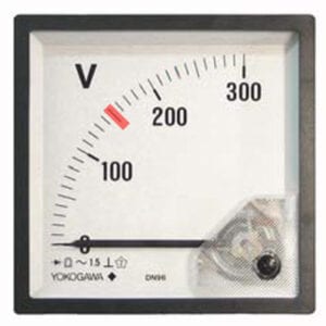
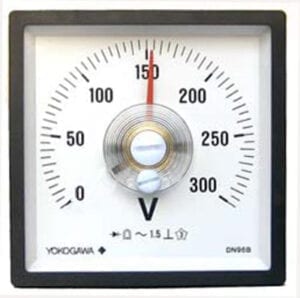 Specified accuracy for most analog meters is 1 to 5% of range. Here is an example of a meter with a 1.5% of range accuracy. With the 300V scale, this calculates to 4.5V. Each scale division equals 5V, so the allowed deviation at any signal level is slightly less than ±1 division. With exactly 150V applied from a calibrator, this meter is at the limit of its accuracy spec.
The second meter also has a 1.5% of range accuracy specification, but only a 90° scale. On this shorter scale each division is 10V, so the allowed ±4.5V deviation is less than half a division in either direction. This is shown in the photo as the superimposed red box at 150V. With such a coarse scale, the precise value is difficult to read. Larger meters and longer scales make it easier to interpolate between scale graduations.
Specified accuracy for digital panel meters is usually between 0.01% to 1% of reading. The digital display requires less interpolation. However range selection does impact reading accuracy. Here is an example of a 3½ digit meter with an accuracy of ±(0.1% of reading + 1 count). A 185mV calibrator signal is applied to the 200mV range. The allowed accuracy breaks down to 0.185mV from the % term and 0.1mV from the counts term – for a total of ±0.285mV, or ±3 counts. This meter is within specification.
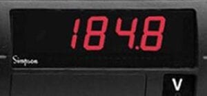
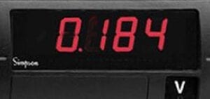
The same signal applied to the 2V range (as shown in the second photo) has a resolution of only 1mV. The allowed accuracy is now 0.185mV from the % term and 1mV from the counts term – for a total of ±1.185mV, or slightly more than ±1 count. On this range the meter is also within specification.
In summary, accuracy specifications provide important information about the performance of meters and instrumentation. Understanding the factors involved and the format of these parameters helps users with equipment selection and application.
