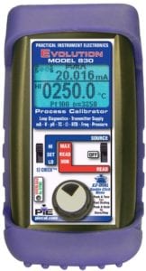
Process calibrators are handheld, battery-powered instruments used for field testing and calibration of industrial process equipment. The typical calibrator has a one or two-parameter digital display, function switch and up/down buttons for output level adjustment. Some models have a dial knob for level adjustment, which many users say is quicker to adjust. Common types of process calibrators are voltage, loop, temperature, and multi-function.

Multi-Function Calibrator

Voltage Calibrator
Process voltage calibrators source DC voltage to check meters and transducer; measure DC voltage to check power supplies and analog outputs. The maximum source output is typically 25-35 Vdc. Measurement range is 30 to 99V full scale (depending on model). Many include milliamp source and measure capability to do basic checks on 4-20 mA devices, which are common in industrial measurement and control applications. Resolution varies from 0.01 V and 0.01mA on basic instruments to 0.001 V and 0.001 mA on more expensive models. Typical accuracies are around 0.05% for V & mA.
Loop calibrators include additional features for more extensive testing and rapid troubleshooting of 4-20 mA current loops. In its basic form, a loop calibrator will check the output of a transmitter (measure mA), simulate a transmitter in the loop (source mA) and provide loop power (24V). In addition to sourcing a selected current value, loop calibrators can sink that current level. This can be viewed as sourcing a negative current, allowing the calibrator to draw the specified value of the current from an external device. In this mode, the calibrator can act as a two-wire transmitter.
The typical calibrator will also source and measure loop current as a percent (e.g. -25 to 125.0% of 4-20mA). In this mode, the 50% point corresponds to 12mA. Automatic output stepping and ramping are other features that speed verification of loop devices.
Two types of temperature calibrators are commonly used in field maintenance: the thermocouple (T/C) calibrator and the resistance temperature detector (RTD) calibrator. The temperature calibrator will measure the temperature sensor output to verify its performance and simulate the sensor output at various temperatures to check a temperature meter or transmitter.
Most T/C calibrators test the popular thermocouple types J, K, T, R, S, and E. Some more advanced models handle up to 15 types, including less common ones such as N, L, B, C and U. To simulate a thermocouple, the calibrator generates a low-level dc voltage (microvolts or millivolts) equivalent to the thermocouple output at the selected temperature. To read a thermocouple, the calibrator measures the thermocouple output, while applying appropriate cold junction compensation.* T/C calibrators also usually have mV source and measure functions.
A dedicated RTD calibrator will usually test platinum (Pt), copper (Cu) and nickel (Ni) RTDs. Popular types for platinum are Pt100/385, Pt100/392 and Pt1000/385, where the first number is the resistance at 0°C and the second number is the alpha. Other popular types are Cu10, Cu50 and Ni120. Unlike a thermocouple, which is a two-wire device, an RTD can be 2-, 3- or 4-wire. Most calibrators can handle all three configurations. The calibrator output for a particular temperature setting depends on the RTD type and the input characteristics of the device under test (such as an RTD thermometer or RTD transmitter).
To generate a resistance signal, the RTD calibrator first determines the resistance value that a particular RTD type (e.g. Pt100/385) would have at the selected temperature. Then it measures the current being supplied from the device under test. The calibrator determines the voltage that this current would generate (V=I*R) and applies that voltage between its output terminals, thus producing the equivalent resistance R = V/I. Note that, to work properly, the current supplied by the device under test must be within the operating range of the calibrator.
In addition to the RTD functions, RTD calibrators usually include resistance measure and simulate capability, up to a few thousand ohms. This is useful for checking continuity, wiring, and load resistance.
For both T/C and RTD calibrators, the typical resolution is 0.1° (C or F). Accuracy varies for each sensor type based on how closely the calibrator matches the standard T/C curve or RTD equation. The best accuracy around room temperature is 0.1°C for a Pt100 RTD or type J thermocouple. Accuracy varies for other sensor types and temperature ranges.
Multi-function calibrators combine the voltage, loop and temperature calibrator functions in one instrument. Advanced multi-function calibrators may add frequency and pulse source/measure (for checking flow meters, speed sensors and similar devices), pH source, pressure measure or a second channel. Many include the ability to store test routines for repeated testing. Extra features in multi-function calibrators vary considerably by manufacturer and model. Some users may benefit from the ability to check for ground faults, do leakage testing, supply isolated power, and act as a temporary replacement for a faulty loop transmitter (so other devices can be tested).
Continuing advances in microprocessor control and reductions in component size have allowed calibrator manufacturers to put even more capability in a handheld device. Recently, several test equipment manufacturers added process calibrator functions to a digital multimeter, potentially eliminating the need to carry a separate calibrator.
Today there is a significant overlap in these calibrator categories and the field service person can get a wide range of capabilities in a handheld instrument. Selecting the right process calibrator requires determining the functions needed, the accuracy required and what additional features will speed field testing and troubleshooting.
*For more info on temperature measurements, see here or shop available process calibrators available from Weschler Instruments.
