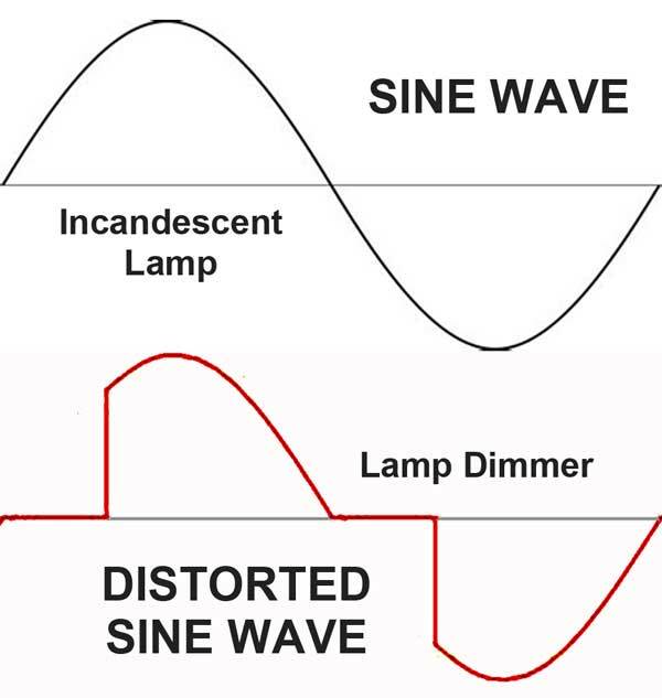
Many AC current sensors work well on sine wave signals but cannot accurately determine the magnitude of distorted waveforms. Variable speed drives, electronic ballasts, LED bulbs, power converters, uninterruptible power supplies, and light dimmers are common sources of distorted current waveforms. Monitoring current in these devices requires careful equipment selection.
 Previous postings discussed general AC current measurements and the types of products available. This article covers TRMS current measurements in power supply (mains) circuits.
Most current sensors respond to the average value of a rectified AC signal (rectified because the average value of an AC waveform is zero). These devices are usually “rms calibrated” – the output is multiplied by 1.11. This corresponds to the heating value of a sinewave. Averaging is inexpensive and provides a quick response. Another inexpensive method is peak detection. A peak-responding sensor captures the maximum value of the input signal and multiplies it by 0.707 to obtain the sine wave rms value. It usually requires low pass filtering to eliminate noise and spikes that can cause erroneous readings. Neither method provides a true representation of the heating value when distortion is present. The True RMS (TRMS) method yields a value that is proportional to the square root of the average of the square of the waveform. TRMS is more accurate on any waveform but generally more expensive. It requires additional components to perform the RMS conversion. A wider bandwidth is needed to handle harmonics without attenuation. A more dynamic range is required to pass the higher peaks of distorted waveforms (crest factor) without clipping.
For portable or temporary applications, a single instrument is typically used to sense, measure and display the TRMS current. Of the 21 product families in the Digital Multimeter category on the Weschler website, 18 are TRMS. Most of these include a 10A AC range. In the Clamp Meter category, 17 of 29 entries are TRMS. Maximum full-scale current varies from 30A to 2000A. An advantage of the single product solutions is that TRMS accuracy, bandwidth and dynamic range are addressed by the instrument manufacturer. For example, the Fluke 115 DMM has a specified AC amps accuracy of 1.5%+3digits, from 45-500Hz, for crest factor <3.
Fixed Installations
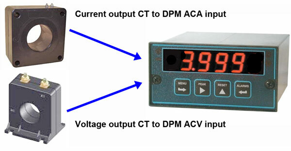 For fixed installations, measurement configuration and instrument selection are more challenging. Currents up to 5 amps can be routed directly through the input of a TRMS responding AC ammeter. Above this level, a current transformer is often inserted to reduce the maximum current to 5A. The CT output connects to either a TRMS AC ammeter (for a current transformer with a 1 or 5A full-scale output), or a TRMS AC voltmeter for a current transformer with a voltage output (typically <1V full scale). Digital panel meters with 3- to 6-digit displays can often be scaled to show the CT input current rather than the meter input current. The current transformer and meter must have sufficient bandwidth to accommodate harmonics, as well as the power line fundamental frequency. The typical instrument-grade current transformer has a frequency range of 50 to 400Hz, which is sufficient to pass the sixth harmonic of a 60Hz mains frequency. A digital panel meter’s burden on the 5A output is usually well below maximum, so the CT has headroom to handle distorted waveform peaks without saturation. Total accuracy is the CT accuracy plus meter accuracy.
A signal conditioning device can be used in place of the meter, to convert the AC signal into another form. Nomenclature varies among manufacturers, so this unit could also be called a transducer, transmitter, isolator or converter. These TRMS examples all have an isolated DC process output:
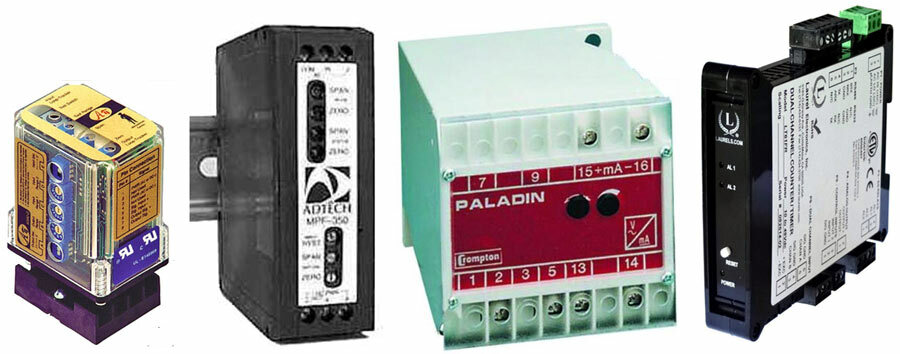 The API 6380G (left) is a plug-in transmitter with 27 input ranges between 50mV and 3V, to easily match the output level of a voltage CT. Eighteen DC output ranges cover 1-10V and 2-20mA. It also accepts an AC current input up to 200mA. However, the burden is too high to use with a current output CT. Next is the Adtech ACX240 Transmitter. This DIN rail unit accepts 1A, 5A, 0.25V and 2.5V AC inputs. Output is 4-20mA and it is powered from 12-43VDC. The Tyco Paladin 253 Transducer has a 5A 60Hz input and a 0-1mA DC output. It is DIN rail mounted and powered from 120VAC. The Laurel LT20 Transmitter (right) is another DIN rail device with 200mV/2V/20mA/5A input ranges. It has a 20mA or 10V analog output, plus relays and RS-485 or Ethernet communications. Power options are AC mains, 12-34VAC or 10-48VDC.
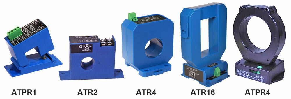 Some manufacturers offer current sensing and TRMS signal conditioners in one unit. These products are easier to specify and simpler to set up than separate pieces from different suppliers. NK Technologies offers an extensive line of average responding and TRMS current transducers, in both solid and split core styles. Models with full-scale currents of 10A to 2000A are available. Some TRMS examples are shown here:
|
Model |
Core |
Max A |
Window |
Output |
Power |
|
ATPR1 |
Split |
50 |
0.85×0.85″ |
5V/10V |
24VDC |
|
ATR2 |
Solid |
200 |
0.75″ |
4-20mA |
Loop |
|
ATR4 |
Solid |
400 |
1.3″ |
4-20mA |
24VDC |
|
ATR16 |
Split |
1600 |
2.3×3.4″ |
4-20mA |
Loop |
|
ATPR4 |
Solid |
2000 |
3.0″ |
4-20mA/5V/10V |
120VAC/24VDC |
True RMS instrumentation may provide a slower response and/or cost slightly more than products with less accurate sensing techniques. However, TRMS is required to accurately monitor modern electronic loads that generate harmonics and distortion, as well as supply circuits in noisy environments.