Alternating current (ac) measurements involve more factors than direct current (dc) measurements. Let’s look at how some of these affect the measurement. We’ll focus on signals with a fundamental frequency below 1kHz. This is where digital multimeters and panel meters are typically used. Higher fundamental frequencies require instrumentation with wider bandwidth, such as audio meters or oscilloscopes.
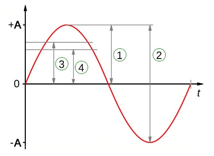 The basic ac waveform is a sine wave with no dc value. In the diagram, 1 indicates the peak amplitude‚ 2 is the peak-to-peak, 3 is the rms value (sometimes described as the heating value), and 4 is the waveform average value. The relationships between these values in a sine wave are:
- peak-to-peak = 2 x peak
rms = 0.707 x peak
average = 0.636 x peak
Many analog and digital meters are average responding but calibrated to display the equivalent rms value for a sine wave. Their accuracy is degraded when measuring distorted (i.e. non-sinusoidal) waveforms. An rms responding meter (often stated as true rms or TRMS) can tolerate some waveform distortion without derating. The amount of distortion is often indicated by a crest factor specification. Crest factor (CF) is the ratio of peak to rms value. The crest factor of a sine wave is 1.414 (the √2). CF of a full-wave rectified sine is also 1.414, but a half-wave rectified sine is 2. The CF of a square wave is 1; triangle wave √3. Low duty cycle pulse trains can have crest factors >10. Some meters will specify an accuracy derating for high crest factor signals.
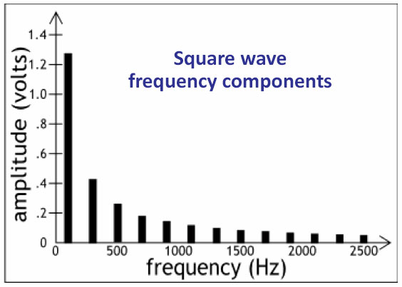
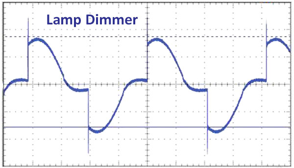
The period is the time to complete one full cycle of the ac waveform. Frequency, expressed in Hertz, is the inverse of the period. Frequency is another factor that affects measurement accuracy. A meter has a bandwidth where the specified accuracy applies. On panel meters intended for measurement of mains circuits, this is often 45-100Hz, with some specialty meters operating down to 25Hz or up to 400Hz. A pure sine wave has only a fundamental frequency. Distortion adds high-frequency components to the signal. These may be beyond the bandwidth of the meter, which will degrade the stated accuracy. For example, a ±1V, 100Hz square wave has a 1.25V peak fundamental at 100Hz and odd harmonics of reduced amplitude at 300, 500, 700Hz, etc. Many electronic lamps and motor controls introduce significant distortion to a sine waveform and are therefore best measured with a TRMS responding meter.
Voltage measurements are made across the load or device under test. Three voltmeter input configurations are frequently used.
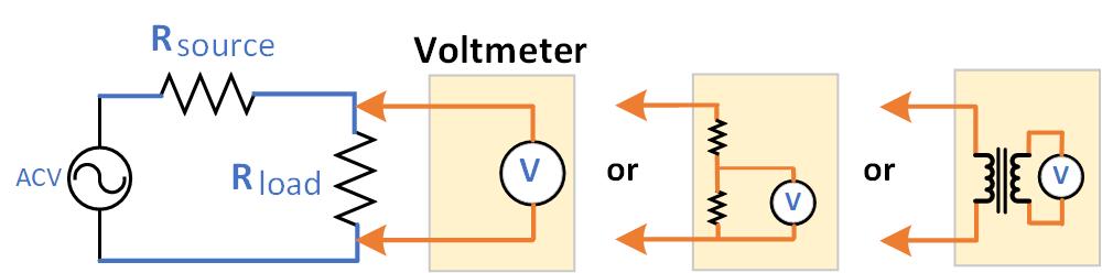
The first voltmeter block shows the meter connected directly across the load. This is typical for an analog meter or digital meter on a range below 4V full scale. An important meter specification for low-frequency signals in this configuration is input resistance. High resistance is desired to avoid altering the voltage across the load. Most voltmeters include a capacitor in series with the meter to block any dc voltage. This allows the meter to display the ac signal even in the presence of a large dc offset. Some TRMS multimeters include an ac+dc function. In this mode, the blocking capacitor is switched out so the meter reads the dc offset and the ac signal together.
The second voltmeter block includes a voltage divider to reduce the meter input to a level compatible with the voltmeter circuit. The sum of the two resistors must be a high value to avoid loading the circuit under test. The third voltmeter scheme is popular in meters dedicated to AC mains measurements, where there is no dc offset. An internal potential transformer reduces the ac signal feeding the meter section and isolates it from the ac source. For these same reasons, some meters are specified for use with an external potential transformer.
Voltmeter Loading Example: A typical DMM has an input resistance on the ac function of 10MΩ. If the circuit being measured has Rsource = 1kΩ and Rload = 10kΩ, connecting that DMM across Rload will change the voltage by <0.01%. However, a meter input resistance of 100kΩ would change the voltage by almost 1%. Fortunately, AC mains circuits have resistances significantly lower than this example, so connecting a voltmeter has a negligible effect.
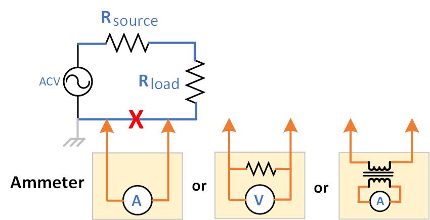 Current measurements are made by placing an ammeter in series with the load. The preferred location for the ammeter is in the low leg of the circuit. This minimizes the voltage at the meter terminals, thus reducing leakage currents to earth (which would cause a reading error). This location also reduces the safety risk to users.
The first ammeter circuit shows a typical analog meter. Here it is important to minimize the resistance the meter adds to the circuit. This is often expressed as a burden, which is the voltage drop across the meter at full-scale current. The second ammeter block shows the configuration of a typical digital meter. A low-value resistor is placed in series with the load and the voltage across that resistor is measured to determine the circuit current. In the third ammeter block, a current transformer reduces the current level and isolates the meter circuitry from the circuit being tested. In some cases, an external current transformer may also be used. Transformer-rated analog ammeters are specified and calibrated for use with an external current transformer.
Ammeter Loading Example: A digital ammeter has an internal resistor of 0.1Ω for the 1A range. A 24V ac circuit drawing 1A has a combined source and load resistance of 24Ω. The addition of the meter resistance decreases the current by 4mA, causing the meter to read low by 0.4%. Using the 10A range with an internal resistor of 0.01Ω would reduce this error. However, accuracy is affected by operating at 10% of full scale.
Careful selection and application of an ac meter, either analog or digital, allows voltage or current measurements with sufficient accuracy for industrial applications. AC power measurements involve the measurement of both voltage and current, plus the phase relationship between them. These more complex measurements are described in several application notes.