Recommended Standard 232 (RS-232) was introduced in the1960s by the telecommunications industry. It defines a simple method for serial communication between a Data Terminal Equipment (DTE) device, such as a computer, and a single Data Communication Equipment (DCE) device, such as a modem or computer peripheral. Originally managed by the Electronics Industry Association (EIA-232), the standard is now maintained by the Telecommunication Industry Association as TIA-232.
Overview
 RS-232 devices use single-ended signaling. Data is sent as a 0 or 1 voltage level, referenced to signal ground. This requires fewer wires to transmit information than the differential signaling used in most serial communication standards. However, single-ended signals are more susceptible to noise and differences in ground voltages between the DTE and DCE. The minimum signal level at the receiver is -3V for a logic 1 and +3V for a logic 0. The maximum is ±25V.
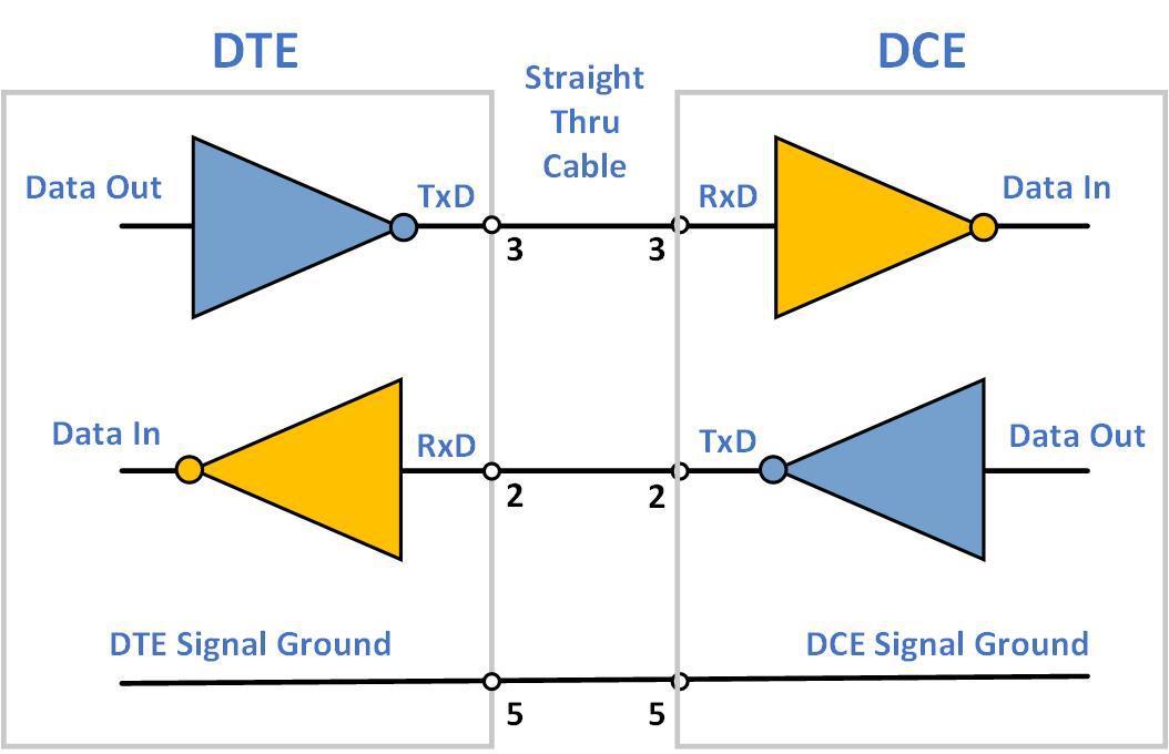
Since transmit and receive are separate circuits, RS-232 can operate in full-duplex mode, supporting concurrent data flow in both directions. The minimum configuration for full-duplex uses 3 wires (see diagram). Half-duplex (one direction data flow) can be achieved with just two wires. Optional flow control can be implemented in hardware or software. Hardware flow control adds the RTS (Request to Send) and CTS (Clear to Send) signals, which increases the wire count to 5 for full-duplex operation.
Data is transmitted in an asynchronous, bit serial format. Although not part of the standard, industry convention is that each character is composed of 1 start bit, 7 or 8 data bits, an optional parity bit and 1 or 2 stop bits. Data format and baud rate are selected as part of the device setup. Baud rate (bits per second) choices are typically 1200, 2400, 4800, 9600, 19200, 38400, 57600, and 115200. The transmitting and receiving devices must operate at the same rate. Some DTE devices can automatically determine the correct rate to use for the DCE device. Not all devices are capable of the higher speeds.
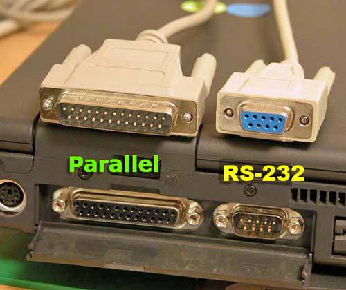
 RS-232 was originally defined with a 25-pin subminiature connector (DB25). Most products only implemented a few of the twenty signals specified in the standard, so a smaller 9-pin DE9 connector was later defined. Terminal numbers on the diagram are for this connector. Pinout for an RJ-45 connector is now also standardized. An RS-232 serial port using the DE9 connector was once standard on most personal computers (see photo). The photo also shows a parallel port with a DB25 connector for comparison. A DTE device normally has a male connector, while the DCE device has a female connector.
The data transmit and receive pins are reversed on the DCE device, allowing use of a straight through (1 to 1) cable between the DTE and the DCE. In situations where both devices are the same type (e.g. both are computers), a null modem (cross-over) cable is used to reverse the data lines and handshake lines in the cable.
The RS-232 standard defines the maximum load capacitance on the signal lines. This generally limits RS232 to 15m (50ft) between transmitter and receiver, at 19200 baud with standard cabling. Longer distances are possible with lower capacitance cables or slower speeds. However, another serial standard may be a better choice in these situations.
Instrumentation
RS-232 interfaces a single DTE to a single DCE. Connecting to multiple instruments requires multiple ports on the computer or controller. For this reason, some industrial PCs include up to four RS-232 ports, or have provisions for adding additional ports via plug-in options. Communicating to an instrument can be straightforward if the manufacturer provides user interface software that runs on a popular platform, such as a Windows PC. During setup, this software may scan the available computer ports to determine where the instrument is connected. Otherwise, the user must manually enter this parameter.
There is no standard protocol defined for RS-232. Each manufacturer or device can have a unique format for commands and data. Without model specific software from the supplier, some level of programming is required to communicate with an RS-232 device. Fortunately, only a few commands and data forms are typically used for each instrument.

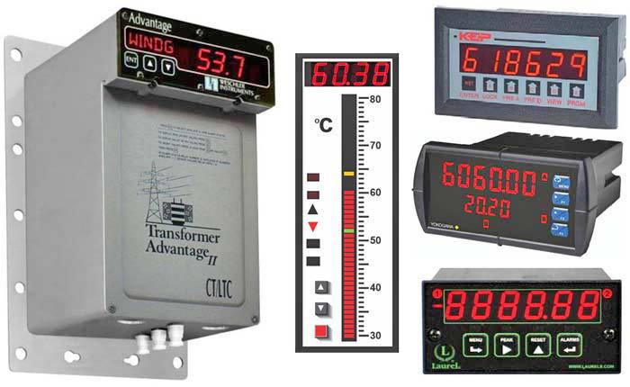
This photo shows a sampling of meters with RS-232 capability, including a substation Transformer Monitor, Bargraph Temperature Meter, Batch Controller, Ammeter and Counter.
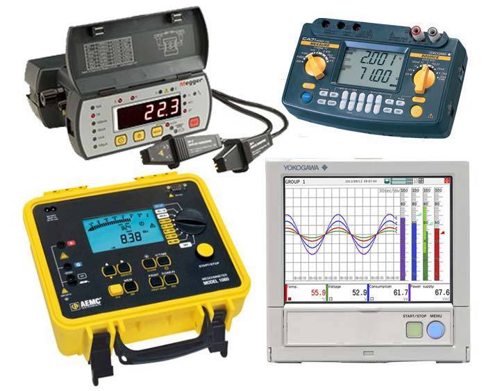
 Portable test instruments with RS-232 capability include (clockwise from upper left) a Microhmmeter, Power Analyzer, Multi-Channel Recorder, and Insulation Resistance Tester. In most cases, the instrument will be the DCE, communicating with a computer. Some instruments can act as the RS-232 DTE, transmitting data to a peripheral for printing, storage, display, etc. An instrument may include isolation on the RS-232 port to eliminate ground problems between the two devices.
Summary
Compared with newer interfaces such as RS-485 and Ethernet, RS-232 has lower transmission speed, shorter maximum cable length, higher voltage swing, larger connectors, and no multipoint capability. In modern personal computers, USB has displaced RS-232 for most peripheral communication. However, thanks to its simplicity and past popularity, RS-232 is still used in industrial machinery, networking equipment, and instrumentation when a short-range, point-to-point, low-speed, wired data connection is adequate. USB to RS-232 converters are readily available to connect a USB computer port to an RS-232 device.
