This year Weschler Instruments celebrates its 80th year as a supplier of meters and instrumentation. Much has changed in electronic measurement equipment and technology since 1941. Vacuum tubes were replaced by transistors and then integrated circuits. Analog indicators became digital readouts and then graphical touchscreens. Manual operation migrated to automatic sequencing and then fully computerized tests. The basic electrical measurements are essentially unchanged: volts, amps, ohms, frequency, watts, etc. However, the range, precision, speed, safety, and ease of use have dramatically improved. Let’s take a brief look at some of the changes in three common field test instruments over the last 80 years.
Oscilloscopes
Early oscilloscopes were large and generally intended for bench use. A few were advertised as portable models, such as the RCA WO-57A (left in the photo, circa 1950). This single-channel instrument featured a 500kHz bandwidth and 3” cathode ray tube. At 10”x13”x8” and 18lbs, it was half the weight of the typical scope at that time.
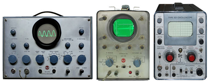 The portable RCA WO-33A (center, 1960) also had a 3” CRT, but an improved 5MHz bandwidth. Weight was down to 12lbs. It could be purchased assembled or in kit form, as could scopes from Eico, Knight and Heath.
Transistors began to replace tubes in the late 1950s, but the high voltage CRT meant most scopes still required AC power. One exception was the Tektronix 321 (right, 1960). This 6MHz, single-channel scope ran 5 hours on 10 Ni-Cad “D” cells. It measured 8”x6”x16” and weighed 16lbs, including batteries.
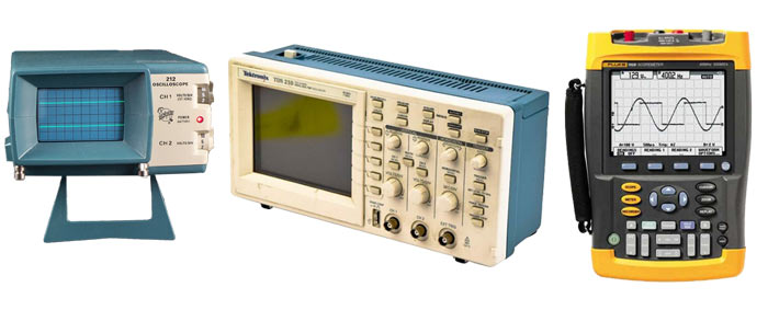 Another exception was the Tektronix 212 (left, 1974). It was a two-channel, 500kHz instrument with a compact 3”x5”x9” size and weight of only 4lbs. Ten internal Ni-Cad “A” batteries provided 3-5 hours of operation.
The first digital storage scopes, introduced by Nicolet in the 1980s, were large and expensive. This technology, combined with advances in LCD displays, eventually allowed manufacturers to eliminate the CRT. The Tektronix TDS210 (center, 1997) had 2 channels with 60MHz bandwidth. Its 6”x12” face and 5” depth provided a large screen. At only 8lbs, it was easily transported but required AC power to operate.
Fluke overcame this limitation with the introduction of their ScopeMeter family. The entry-level Fluke 192 (right, 1990) was a two-channel, 60MHz model with a monochrome LCD display. Other models offered up to 4 channels, 200MHz BW and a color display. At 10”x8”x2.5” and 4.5lbs, they were rugged, convenient to carry and easy to use. NiMH batteries provided 4 hours of operation. Soon Fluke and other manufacturers introduced more models with a similar form factor.
Multimeters
US soldiers in World War II used the Simpson 260 (left in the photo) for field service work. This rugged volt-ohm-milliammeter (VOM) had 20 ranges and a higher input sensitivity than earlier VOMs (20kΩ/V on DC and 1kΩ/V on AC). It needed no power for voltage and current measurements but used a dry cell battery for the ohms function. The 260 became an industry standard and is still manufactured in 9 versions, including one in the original bakelite case.
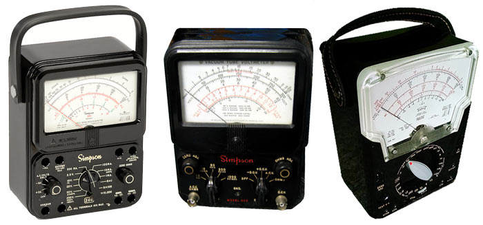 To meet the need for additional resolution and less circuit loading, the vacuum tube voltmeter (VTVM) became a popular service tool in the 1950s. The Simpson 303 (center, circa 1950) had a 10MΩ input impedance on DC and included ACV measurement to 100kHz. It offered an optional RF probe and was housed in a portable bakelite case. However, it required AC power.
This limitation was overcome a few years later by the introduction of battery-powered VTVMs, such as the Triplett 631 (right, 1955). This model offered combined VTVM/VOM operation and boasted 32 ranges. The plate voltage for the 1R5 vacuum tube was supplied by two 22.5V “B” batteries.
In the 1960s, the field-effect transistor (FET) replaced the vacuum tube. FET input analog multimeters offered high input impedance while operating from a 9V battery. Many used a single “C” cell for the ohms function.
Non-Linear Systems (NLS) was an early innovator of digital multimeters (DMMs). The X-2 model (left, 1966) was a benchtop unit that measured DCV, ACV & ohms. Its transistor circuitry and nixie tube display required AC power.
 In the early 1970s, the light-emitting diode became the preferred display technology for instrumentation. The seven-segment LED allowed benchtop DMM capability to fit in a portable unit. The Beckman 280 (center, 1973) was one of the first handheld digital multimeters. It had five functions with 4 DC/AC voltage ranges, 4 DC/AC current ranges and 6 ohms ranges. The 280 was powered by 4 “C” batteries.
Fluke used technology advances in liquid crystal displays and custom integrated circuits to introduce the 8020 DMM (right, 1977). This 3.5 digit, 5 function meter ran 200 hours on a single 9V battery and quickly became the industry standard for handheld multimeters.
Today handheld DMMs are made by dozens of companies throughout the world. A wide variety of models offer an increased resolution, additional ranges, and many other functions. Some models display multiple parameters, include a bargraph indicator or graph readings vs time. Datalogging multimeters store many readings for archiving or export to a computer.
Clamp Meters
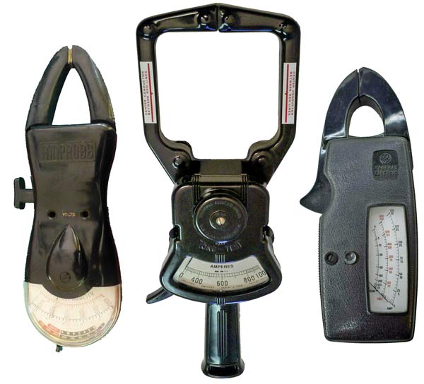 A clamp meter simplifies AC current measurements by inductively sensing the current flow in a conductor. This eliminates breaking the test circuit, as is required when using a standard ammeter. Pyramid Amprobe introduced one of the first multifunction clamp meters. Their Model 300 AC Volt-Ammeter (left, 1950) measured up to 600VAC using normal test leads and up to 300AAC by placing the jaws around the conductor. Other models in the series had larger jaws and measured up to 1200A.
The Columbia Clamp-On Tong Test Ammeter (center) used an iron vane movement to sense AC and DC current. Ten plug-in range modules measured the true RMS value from 75A to 1000A full scale. It was based on a Crompton Parkinson design from the 1930s. Weschler continued to manufacture this unique meter until 2018.
A popular analog clamp meter in the 1960s was the GE 942D Snapper (right). It measured AC with two voltage and two current ranges. The 150A model is shown here. The 300A model had larger jaws. Both included a 1kΩ resistance range.
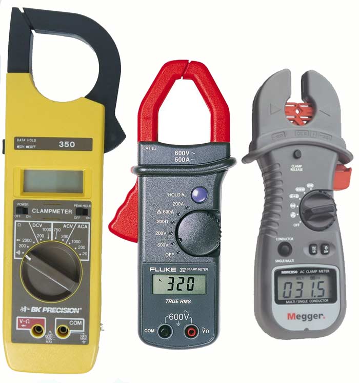 The B&K 350 (left, 1989) was an early digital clamp meter. It had a 3.5 digit LCD display and operated from a 9V battery. This instrument measured to 1000VDC in 2 ranges, 750VAC in 2 ranges, 1000AAC in 3 ranges and 2000 ohms in 2 ranges. The AC was average responding. A later 350B model also included frequency to 32kHz.
The Fluke Model 30 (center, 1995) digital clamp meter included ACV measurements to 600V, AC current to 400A and a 200Ω resistance range. It had a 2000 count LCD display and CAT III, 600V rating. Other models in the family offered TRMS measurements and higher full-scale currents.
As the popularity of the clamp meter increased, many manufacturers introduced models with additional functions and ranges. Now a clamp meter is often carried in place of a traditional DMM. A number of specialized clamp meters have been introduced in the last 20 years. The Megger MMC850 (right, 2005) used multiple magnetic sensors to measure current in two and three-conductor cables without the need to split out one conductor. It was a single function instrument that measured 200A on 45-400Hz circuits. Other examples of specialized clamp meters include leakage testers, power meters, power quality analyzers, ground resistance testers, and thermal imaging clamp meters.
In a future article, we will look at some of the changes in panel instrumentation since 1941.
