Many digital meters provide relay outputs to activate external alarms or controls. Two parameters, setpoint and hysteresis, are used to configure these outputs. The setpoint is a predetermined level, within the range of the meter, where a protective or control action is initiated.
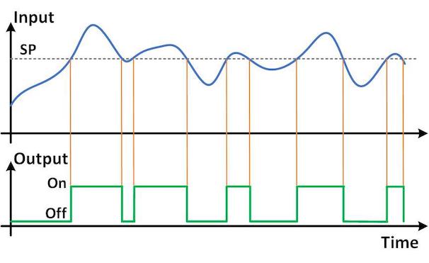 In measurement and control literature, the term is often written as a single word – setpoint. This diagram shows a high-acting output that is on when the input signal is above the setpoint (SP) value. If the input is near the setpoint value, a small change in signal level or noise can cause an output transition, either on or off. Frequent output cycling may lead to excessive wear on relay contacts, motors, pumps and other system components, as well as control system instability. If the output is being used as an alarm, an erratic alarm operation could occur.
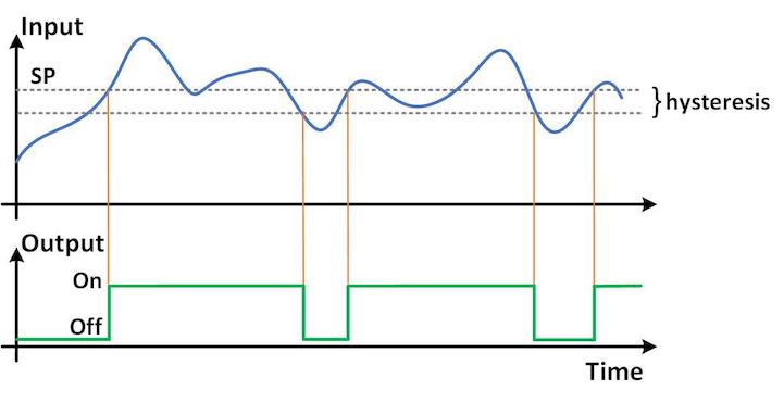
To reduce these effects, hysteresis is usually added. Setpoint hysteresis is the difference in the transition level when approached from opposite directions. This region is sometimes called the deadband because no action takes place between the two levels. For a high-acting output, the ‘on’ transition occurs when an input that is below the setpoint reaches the setpoint level (input= setpoint). The ‘off’ transition occurs when an input that was previously above the setpoint reaches a value of setpoint minus hysteresis (input= setpoint-hysteresis). For the sample waveform, a small amount of hysteresis cuts the number of output transitions in half.
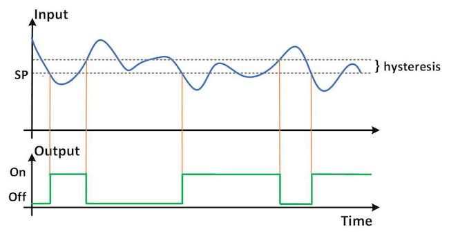 Digital meters often allow the user to configure an output as either high or low acting. For a low-acting setpoint, the control action is reversed. The ‘on’ transition occurs when an input that is above the setpoint drops to the setpoint level (input= setpoint). The ‘off’ transition occurs when an input that was previously below the setpoint reaches a value of setpoint plus hysteresis (input= setpoint+hysteresis).
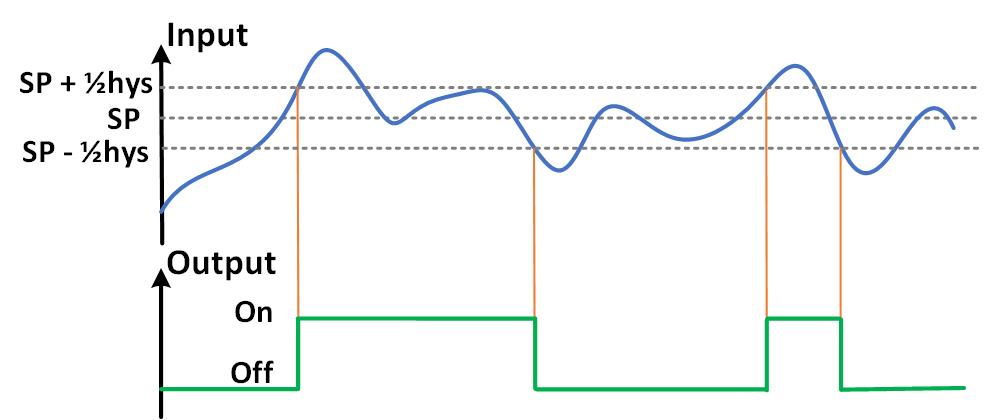
The user is typically asked to enter setpoint and hysteresis values for each output during the meter setup. The standard format for specifying setpoint on a fixed-range meter is to enter the number of counts. The method for specifying hysteresis, however, varies by manufacturer and model. The method shown above is typically described as single-sided or unbalanced hysteresis. Another method uses a split or balanced formula. No output change in either direction occurs at the setpoint value. For a high setpoint, the ‘on’ transition occurs at a level of setpoint + ½hysteresis. The ‘off’ transition occurs at a value of setpoint – ½hysteresis.
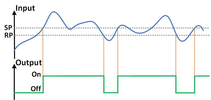 A few manufacturers avoid this issue by requiring direct entry of the reset value (RP). The hysteresis is the difference between the two numbers. The user must set the RP below the SP for high-acting outputs and above the SP for low-acting outputs. One disadvantage of this method, however, is that a change to setpoint value also requires a change to the reset value.
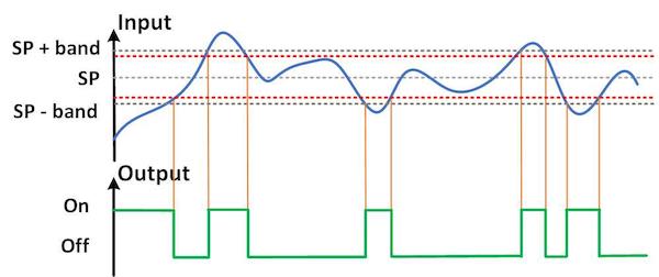 Another method for specifying output operation is to define a window or band. For an inside-acting band, the output is ‘on’ when the input signal is inside the band. For an outside-acting band, the output is ‘on’ when the signal is outside the band. A typical application for an outside-acting band is to use a single alarm to indicate when the input is either too high or too low. Hysteresis is typically added for the same reasons as described earlier. For an outside band with hysteresis, the output activation levels are unchanged at SP+band and SP-band. The release points, however, shift by the amount of hysteresis. The upper release level is SP+band-hysteresis (upper red line in the diagram). The lower release level is SP-band+hysteresis (lower red line).
This brief article covers the more popular ways that setpoints and hysteresis are defined and operate in digital panel meters. Other less common schemes may also be employed. Some meters (particularly temperature controllers) use a mix of methods – the split method for control outputs and the single-sided method for alarm outputs. Advanced meters may even give the user a choice of method. Close reading of a meter’s instruction manual is usually needed to determine exactly how the setpoint and hysteresis capabilities are implemented. If the wrong method is assumed, the meter outputs will not perform as expected.